background image

Development Kit 

2.6.3 SW1-4, SW1-5 Options 

SW1-5 controls the routing of the CP3 (Configurable Pin 3) signal from the XPort™. CP3 is 
connected to pin 8 of the XPort™ and can be software configured as RTS, LED3, DTR, IN3, 
or OUT3. With SW1-5 in the OFF position, the CP3 signal is routed to SW1-4.    

SW1-4 and SW1-5 are inputs to the PLD which does the actual switching. The drawings 
represent the logical switching functions. 

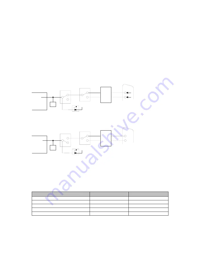
CP3 options are a little more complicated because both SW1-4 and SW1-5 are used in the 
configuration setup. In this drawing, SW1-5 is OFF, which connects XPort™ pin-8 to the 
RS232 transceiver. The XPort™ Configurable Pin 3 (CP3) is configured for RTS. SW1-4 is 
ON, which will route the signal from XPort™ pin-8 to P1 pin-7 (RTS).  

8

MAX232

DB-9

P1

7

RTS

RS232

TTL

4

DTR

CP3

RTS

LED3
DTR

IN3

OUT3

SW1-4

PLD

OFF

ON

SW1-5

PLD

OFF

ON

XPort

JP4 - PIO 

HEADER

6

CP3 LED

3.3v


In the next drawing, SW1-5 is ON, which disconnects XPort™ pin-8 from reaching the 
RS232 transceiver. The XPort™ Configurable Pin 3 (CP3) is configured for LED3. 

8

MAX232

DB-9

P1

7

RTS

RS232

TTL

4

DTR

CP3

LED3

RTS
DTR

IN3

OUT3

SW1-4

PLD

OFF

ON

SW1-5

PLD

OFF

ON

XPort

JP4 - PIO 

HEADER

6

CP3 LED

3.3v


When Configurable Pin 3 is configured for LED3, it functions as a diagnostic indicator. The 
LED3 signal in combination with the LED1 signal will indicate diagnostic information as 
shown in the following table.   

Note:

 CP1 must be configured for LED1 and CP3 must be configured for LED 3 for 

diagnostic mode. 

Table 7 - LED States 

Condition 

CP3 LED (LED3) 

CP1 LED (LED1) 

No Errors 

OFF 

ON 

Network controller error 

ON 

Blink 3x / 4 sec OFF 

Duplicate IP address present 

ON 

Blink 5x / 4 sec OFF 

No DHCP response 

Blink 2x /sec 

Blink 5x / 4 sec OFF 

Setup menu active  

Blink 2x / sec 

See Note 

Note:

 During a Telnet connection, CP1 LED (LED1) will be ON. For a serial port connection, 

CP1 LED (LED 1) is blinking for 2 sec, then OFF for two seconds. (It appears as 4 blinks, 
then OFF for 2 seconds) 

CTS and RTS work together for hardware flow control. Configurable Pin 3 (CP3) should be 
configured as RTS when Configurable Pin 1 (CP1) is configured as CTS. Select hardware 
flow control as described in 

Flow

 on page 

4-12

See 

OEM Configurable Pins

 on page 

6-13

 for configuring CP3 as IN3 or OUT3.  

XPort™ User Manual and Development Kit 

2-7 

Содержание XPort

Страница 1: ...User Manual and Development Kit Part Number 900 270 Revision B 7 03 ...

Страница 2: ......

Страница 3: ...ered trademark of The Open Group Windows 95 Windows 98 Windows 2000 Windows NT and Windows XP are trademarks of Microsoft Corp Netscape is a trademark of Netscape Communications Corporation 15353 Barranca Parkway Irvine CA 92618 USA Phone 949 453 3990 Fax 949 453 3995 Technical Support Phone 800 422 7044 or 949 453 7198 Fax 949 450 7226 On line www lantronix com support Sales Offices For a current...

Страница 4: ...nerates uses and can radiate radio frequency energy and if not installed and used in accordance with this guide may cause harmful interference to radio communications Changes or modifications to this device not explicitly approved by Lantronix will void the user s authority to operate this device Attention With the purchase of XPort the OEM agrees to an OEM firmware license agreement that grants t...

Страница 5: ...onducted RF Emissions Telecom Lines 150KHz 30MHz FCC Part 15 Subpart B Class B IEC 1000 3 2 A14 2000 IEC 1000 3 3 1994 Electromagnetic Immunity EN55024 1998 Information Technology Equipment Immunity Characteristics Direct ESD Contact Discharge Indirect ESD Radiated RF Electromagnetic Field Test Electrical Fast Transient Burst Immunity RF Common Mode Conducted Susceptibility Power Frequency Magneti...

Страница 6: ...n no event will Lantronix be responsible to the user in contract in tort including negligence strict liability or otherwise for any special indirect incidental or consequential damage or loss of equipment plant or power system cost of capital loss of profits or revenues cost of replacement power additional expenses in the use of existing software hardware equipment or facilities or claims against ...

Страница 7: ...1 10 Technical Specifications 1 6 2 Development Kit 2 1 2 1 Introduction 2 1 2 1 1 Major Components 2 2 2 2 Serial RS232 Interface 2 3 2 3 RS232 Port 2 3 2 4 Power Supply 2 3 2 5 General Control PLD 2 3 2 6 Configuration Switch Bank 2 4 2 6 1 SW1 2 Options 2 5 2 6 2 SW1 3 Options 2 6 2 6 3 SW1 4 SW1 5 Options 2 7 2 6 4 Configurable Pins Interface Header JP4 2 8 2 7 Timer 2 8 2 8 Board Layout 2 9 2...

Страница 8: ...er Configuration Network Configuration 4 9 4 5 1 IP Address 4 9 4 5 2 Set Gateway IP Address 4 10 4 5 3 Netmask Number of Bits for Host Part 4 10 4 5 4 Change Telnet configuration password 4 10 4 5 5 DHCP Naming 4 11 4 6 Channel 1 Configuration Serial Port Parameters 4 11 4 6 1 Baudrate 4 11 4 6 2 I F Interface Mode 4 12 4 6 3 Flow 4 12 4 6 4 Port Number 4 12 4 6 5 Connect Mode 4 14 4 6 6 Remote I...

Страница 9: ...earch for Device 6 1 6 1 2 Assign IP Address 6 2 6 1 3 Add Remote Device 6 2 6 1 4 Ping 6 2 6 2 Setting Parameters 6 3 6 3 List View 6 5 6 4 Upgrade 6 6 6 5 Telnet 6 7 6 6 Web Interface 6 7 6 7 Recovering Firmware 6 8 6 8 Loading and Saving 6 8 6 9 Printing 6 9 6 9 1 Print Preview 6 9 6 10 Device Configuration Reference 6 10 6 10 1 E mail Notification 6 10 6 10 2 E mail Recipients Collection 6 11 ...

Страница 10: ...ptions 10 11 11 IP Addresses 11 1 11 1 Network Portion 11 1 11 2 Subnet Portion 11 1 11 3 Host Portion 11 1 11 4 Network Address 11 2 11 5 Broadcast Address 11 2 11 6 IP Subnet Mask 11 2 11 7 Private IP Networks and the Internet 11 2 11 8 Network RFCs 11 3 12 Glossary 12 1 List of Figures Figure 1 Evaluation Board Block Diagram 2 2 Figure 2 Evaluation Board Connected to Serial Device and Network 3...

Страница 11: ...ush Mode Options 4 20 Table 19 Pack Control Options 4 21 Table 20 Protocol Firmware 5 1 Table 21 Problems and Error Messages 7 2 Table 22 Monitor Mode Commands 8 3 Table 23 Command Response Codes 8 3 Table 24 UDP Configuration 9 1 Table 25 Block Types 9 4 Table 26 Setup Record Construction 9 5 Table 27 Channel Parameters 9 6 Table 28 Baud Rate Settings 9 7 Table 29 Binary to Hexadecimal Conversion...

Страница 12: ......

Страница 13: ...tures The XPort device server is a miniaturized version of a modular serial to Ethernet converter based in principle on an existing Lantronix Modular Serial to Ethernet module The XPort device server package contains a DSTni LX controller with 256K bytes of SRAM 2K bytes of boot ROM and integrated AMD 10 100 PHY The package also contains a 3 3 volt serial interface 4 Mbit flash memory Ethernet mag...

Страница 14: ...col UDP for typical datagram applications in which devices interact with other devices without maintaining a point to point connection SMTP for e mail transmission 1 3 XPort Block Diagram 2 5V Power Supply Filter 3 3V 2 5V 3 3V Digital 3 3V Analog DSTni LX PHY TXD RXD RTS CTS DTR CTS DCD CS Serial Interface Serial 4 Mbit Flash SCLK MOSI MISO Reset Magnetics LEDs TX TX RX RX LEDs 48MHz Crystal LX 2...

Страница 15: ... CP1 Configurable Pin 1 6 Configurable Pin 1 can be configured as Flow control connects to CTS of attached DTE device Programmable Digital Input or Output Status LED 1 CP2 Configurable Pin 2 7 Configurable Pin 2 can be configured as Modem control connects to DCD of attached DTE device Programmable Digital Input or Output CP3 Configurable Pin 3 8 Configurable Pin 3 can be configured as Flow control...

Страница 16: ...uplex Link Off Blinking Green 100BASE T Full Duplex Activity Solid Amber Off 10BASE T Half Duplex Link Blinking Amber Off 10BASE T Half Duplex Activity Solid Green Off 10BASE T Full Duplex Link Blinking Green Off 10BASE T Full Duplex Activity 1 7 Dimensions The XPort dimensions are shown in the following drawing RIGHT LED 18 25 0 719 16 25 0 640 11 55 0 455 7 15 0 281 CONTACT 1 CONTACT 8 5 85 0 23...

Страница 17: ...e pattern and mounting dimensions for the XPort device server are shown in the following drawing 16 05 0 632 12 30 0 484 10 84 0 427 6 35 0 250 2 54 0 100 O 3 25 0 128 O O 0 90 0 035 O 1 60 0 063 2 8 1 7 1 27 0 050 2 54 0 100 FRONT O 11 90 0 468 DIMS mm in SHIELD TAB TOLERANCE XX 0 05 0 002 1 9 Product Information Label The product information label contains important information about your specif...

Страница 18: ...Pins 6 8 can also drive external LEDs for XPort status diagnostics Management Internal web server SNMP read only Serial login Telnet login Security Password protection Locking features optional Rijndael 128 bit encryption Internal Web Server Serves static web pages and Java applets Storage capacity 384KBytes Weight 0 34 oz 9 6 grams Material Metal shell thermoplastic case Temperature Operating ran...

Страница 19: ...at 7 Serial Adaptor 25 pin to 9 pin 2 1 Introduction The XPort Evaluation Board provides a test or evaluation platform for the Lantronix XPort device server The XPort Evaluation Board supplies an RS232 serial interface to 3 3V CMOS level interface connection for the XPort server It also supplies the required XPort device server with 3 3V A programmable Logic Device PLD reset push button switch DIP...

Страница 20: ...witch outputs are used as inputs to the PLD to select the desired mode of operation TP8 TP9 XPort DIP SWITCH RESET 5 VDC IN 3 3V POWER PIO RS232 PLD TMR LEDs SLOW PWR LED RTS DCD DTR CTS PLD HEADER RXD TXD SWITCH RESET PADS JP3 JP4 J1 D2 SW1 SW2 DB 9F TP13 TP11 RTS DTR CTS DCD Figure 2 1 Evaluation Board Block Diagram 2 1 1 Major Components The major components of the evaluation board include RS23...

Страница 21: ... capability of true RS232 level performance from a 3 3V input power source and for its 15kV ESD protection The part also includes a RS232 valid output that is used to light an LED via the PLD circuit 2 4 Power Supply The Evaluation Board contains a 3 3V regulator that receives input power via a 2 5mm input power jack The input power should be 5VDC from a regulated DC source A 5VDC power module is ...

Страница 22: ...ed DTE device through DB 9 pin 8 Use this if CP1 is set up for hardware flow control 2 ON XPort CP1 pin 6 not connected to RS232 transceiver Use this if CP1 is set up as a IN1 OUT1 or LED1 OFF XPort CP2 pin 7 is connected to the RS232 transceiver which connects to DCD of an attached DTE device through DB9 pin 1 Use this if CP2 is set up for hardware handshaking 3 ON CP2 pin 7 is not connected to t...

Страница 23: ...the next drawing SW1 2 is ON which disconnects pin 6 from the RS232 transceiver The XPort Configurable Pin 1 CP1 is configured for LED1 XPort 6 CP1 JP4 PIO HEADER 4 MAX232 DB 9 P1 8 CTS RS232 LED1 IN1 OUT1 CTS CP1 LED SW1 2 PLD OFF ON 3 3v When Configurable Pin 1 is configured for LED1 it will function as a status indicator for the serial port Condition CP1 LED State Idle Channel Solid on Connecte...

Страница 24: ...connects XPort pin 7 to the RS232 transceiver The XPort Configurable Pin 2 CP2 is configured for DCD 7 DB 9 P1 1 DCD CP2 DCD IN2 OUT2 MAX232 RS232 SW1 3 PLD OFF ON XPort CP2 LED 3 3v JP4 PIO HEADER 2 In this drawing SW1 3 is ON which disconnects XPort pin 7 from the RS232 transceiver The XPort Configurable Pin 2 CP2 is configured for OUT2 OUT2 IN2 DCD 7 DB 9 P1 1 DCD CP2 MAX232 RS232 SW1 3 PLD OFF...

Страница 25: ... MAX232 DB 9 P1 7 RTS RS232 TTL 4 DTR CP3 LED3 RTS DTR IN3 OUT3 SW1 4 PLD OFF ON SW1 5 PLD OFF ON XPort JP4 PIO HEADER 6 CP3 LED 3 3v When Configurable Pin 3 is configured for LED3 it functions as a diagnostic indicator The LED3 signal in combination with the LED1 signal will indicate diagnostic information as shown in the following table Note CP1 must be configured for LED1 and CP3 must be config...

Страница 26: ... 6 JP4 Pin Connects To 1 3 3V 2 XPort Pin 7 CP2 3 Signal Ground 4 XPort Pin 6 CP1 5 External Reset XPort Pin 3 6 XPort Pin 8 CP3 2 7 Timer The timer circuit is a National LMC555 IC The purpose of the timer is to generate a timer clock approximately 10 counts per second This clock is routed to the input clock pin of the PLD to be used for state machine and counter functions 2 8 XPort User Manual an...

Страница 27: ...2 Transceiver U2 P1 1 RS232 to DTE Device TP7 Chassis Ground D2 Reset XPort Power 5VDC In J1 XPort D Out XPort D In JP3 R31 Chassis Ground Table 8 Component Identifier Label Function Label Function P1 RS232 Interface DB 9F Connector TP1 NA J1 5VDC Input Connector TP2 NA SC1 NA TP3 NA SW1 Mode Switch TP4 NA SW2 Reset Switch TP5 Chassis Ground D2 XPort Power Red LED TP6 Chassis Ground D4 RS232 Valid...

Страница 28: ......

Страница 29: ...e system manager will not be able to access the unit This port can also be password protected 3 1 Addresses and Port Number The Ethernet address is also referred to as the hardware address or the MAC address The first three bytes of the Ethernet Address are fixed and read 00 20 4A identifying the unit as a Lantronix product The fourth fifth and sixth bytes are unique numbers assigned to each unit ...

Страница 30: ...Note The required input voltage for the XPort Evaluation Board is 5VDC 3 W maximum 4 Supply power to the serial device 3 3 Methods of Assigning the IP Address The unit s IP address must be configured before a network connection is available You have several options for assigning an IP to your unit however we recommend XPort Installer on page 3 5 Method Description DHCP A DHCP server automatically ...

Страница 31: ... unit with an IP address gateway address and subnet mask when the unit boots up You can use the XPort Installer software to search the network for the IP address your unit has been assigned by the DHCP server and add it to the managed list See XPort Installer later in this chapter Note This DHCP address will not appear in the unit s standard configuration screens You can however determine your uni...

Страница 32: ...on the same network to see whether the selected address is being used If the selected address is not in use then the unit uses it for local subnet communication If another device is using the selected IP address the unit selects another address from the AutoIP range and reboots itself After reboot the unit sends out another ARP request to see if the selected address is in use and so on AutoIP is n...

Страница 33: ...1 Insert the product CD into your CD ROM drive The CD will automatically start and display the main window If the CD does not launch automatically a Click the Start button on the Task Bar and select Run b Enter your CD drive letter colon backslash Launch exe e g D Launch exe Figure 3 2 XPort Developer Kit Window 2 Click the XPort Installer button The installation wizard window displays 3 Respond t...

Страница 34: ...P server The device IP Address is normally set to 0 0 0 0 at the factory The Hardware Address is an individual permanent address assigned to a particular device on the network The Hardware Address can be found on the product label If a device doesn t show up after searching then the device might not have a valid IP address assigned Use the Assign IP Address feature to set a specific IP address on ...

Страница 35: ...he main window 3 4 4 Test the IP Address 1 To test the IP Address select the device from the main window list then click the Ping icon or select Ping from the Action menu The Ping Device dialog box shows the IP Address of the selected device Click the Ping button and the results will be displayed in the Status window Use the Clear Status button to clear the window so you can Ping the device again ...

Страница 36: ...de window in a Telnet session To configure the unit via a Web browser first click on one of the devices listed in the window then click the Web icon The Lantronix Web Manager window displays in your browser For Web Configuration see Web Manager Page on page 4 2 To configure the unit via a Telnet session first click on one of the devices listed in the window then click the Telnet icon The Setup Mod...

Страница 37: ... 1 The connection will fail quickly but the unit will temporarily change its IP address to the one designated in this step telnet 191 12 3 77 1 4 Finally open a Telnet connection to port 9999 and press Enter within three seconds to go into Setup Mode If you wait longer than three seconds the unit will reboot telnet 191 12 3 77 9999 5 Set all required parameters Note The IP address you just set is ...

Страница 38: ......

Страница 39: ... device Your device may have different configuration options 4 1 Configuring via Web Browser Open your JAVA enabled web browser and enter the IP address The Lantronix Web Manager page will display Go to Web Manager Page on page 4 2 for a summary of the menu selections 4 2 Using XPort Installer XPort Installer is a powerful software utility for configuring device servers from a network connection T...

Страница 40: ...ge will display Figure 4 2 Lantronix Web Manager Web Manager has the following buttons Unit Configuration Server Properties Port Properties Factory Settings1 Update Settings Channel1 1 Use the menu pushbuttons to navigate to sub pages where you can configure server settings See explanations of the configuration parameters later in this chapter 2 When you are finished click the Update Settings butt...

Страница 41: ...e Server Configuration and the Port Configuration settings These are static settings read from the device Note The following screen shots represent typical web pages See the Lantronix web page for the latest version The following two pictures show the information available in the above screen shot XPort User Manual and Development Kit 4 3 ...

Страница 42: ...Telnet Password field enter a password to prevent unauthorized access to the Setup Mode via a Telnet connection to port 9999 The password is limited to 4 characters An enhanced password setting of 16 characters is available under Security Settings on the Telnet Setup Mode window Note No password is required to access the Setup Mode window via a serial connection 4 3 4 Port Properties Serial Protoc...

Страница 43: ... Incoming DTR Never accept incoming Response Nothing quiet Character Response Startup No Active Connection startup With Any Character With CR 0x0D Only Manual Connection Autostart Modem Mode With Active DTR Remote IP Address user selectable Remote Port user selectable Local Port 10001 default 10001 user selectable On Active Connection Enable Disable On Passive Connection Enable Disable At Time To ...

Страница 44: ...ter 02 User Selectable Disconnect Mode Ignore DTR With DTR Drop Check for CTRL D to Disconnect Enable Disable Port Password Enable Disable Telnet Mode Enable Disable Inactivity Timeout Enable Disable Inactivity Timer User Selectable Port Password User Selectable Port Password must be enabled 4 3 5 Factory Settings1 Click this button to set Channel1 to the factory default settings 4 3 6 Update Sett...

Страница 45: ...r telnet x x x x 9999 Note Be sure to include a space between the IP address and 9999 2 Click OK 3 The Setup Mode window displays MAC address 00204A4113A3 Software version 01 0b9 021219 XPT Press Enter to go into Setup Mode 4 To enter the Setup Mode you must press Enter within 5 seconds The configuration settings will appear 5 Select an option on the menu by entering the number of the option in th...

Страница 46: ...abled Channel 1 Baudrate 9600 I F Mode 4C Flow 00 Port 10001 Remote IP Adr none Port 00000 Connect Mode C0 Disconn Mode 00 Flush Mode 00 Expert TCP Keepalive 45s ARP cache timeout 600s E mail Mail server 0 0 0 0 Unit Domain Recipient 1 Recipient 2 Trigger 1 Serial Sequence 00 00 CP1 X CP2 X CP3 X Message Priority L Min notification interval 1 s Re notification interval 0 s Trigger 2 Serial Sequenc...

Страница 47: ...reset button or cycling the unit s power power off and back on The self test will begin You have one second to enter three lowercase x characters xxx Note The easiest way to enter Setup Mode is to hold down the x key at the terminal or emulation while resetting the unit 3 At this point the screen display is the same as when you use a Telnet connection To continue with a serial port login go to Usi...

Страница 48: ...yed for example 255 255 255 0 Table 9 Standard IP Network Netmasks Network Class Host Bits Netmask A 24 255 0 0 0 B 16 255 255 0 0 C 8 255 255 255 0 Table 10 Netmask Examples Netmask Host Bits 255 255 255 252 2 255 255 255 248 3 255 255 255 240 4 255 255 255 224 5 255 255 255 192 6 255 255 255 128 7 255 255 255 0 8 255 255 254 0 9 255 255 252 0 10 255 255 248 0 11 255 128 0 0 23 255 0 0 0 24 4 5 4...

Страница 49: ... LTX 3 Numeric DHCP name You are able to change the DHCP name by specifying the last octet of the IP address When you use this method the DHCP name will be LTXYY where YY is what you chose for the last octet of the IP address If the IP address you specify is 0 0 0 12 then the DHCP name will be LTX12 This method will only work with 2 digit numbers 0 99 4 6 Channel 1 Configuration Serial Port Parame...

Страница 50: ... Common I F Mode Setting Binary Hex RS 232C 8 bit No Parity 1 stop bit 0100 1100 4C RS 232C 7 bit Even Parity 1 stop bit 0111 1000 78 4 6 3 Flow Flow control sets the local handshaking method for stopping serial input output Generally flow control is not required if the connection is used to pass a blocked protocol with block sizes less than 1k ACK NAK and or speeds of 19200 or less Use the follow...

Страница 51: ... Incoming TCP UDP port and Outgoing TCP UDP source port Port 0 is used when you want the outgoing source port to change with each connection If the port number is set to 0 the initial value of 5000 will be used to actively establish a connection Each subsequent connection will increment the number by 1 When the port number reaches 7999 it will wrap back to 5000 The automatic port increment feature...

Страница 52: ...0 1 0 With Carriage Return 0x0D only 0 0 1 1 Manual connection 0 1 0 0 Autostart 0 1 0 1 Hostlist 0 0 1 0 Datagram Type Directed UDP 1 1 0 0 Modem Mode Full Verbose 1 0 1 1 0 Without Echo 0 0 1 1 0 1 character Response 1 0 1 1 1 INCOMING CONNECTION Never Accept Incoming rejects all external connection attempts Accept with DTR Active accept external connection requests only when the DTR input is as...

Страница 53: ...5 and must be preceded by a forward slash ASCII 0x2F The slash separates the IP address and the port number If the port number is omitted from a command string the internally stored remote port number is used to start a connection For Active Start options requiring internally stored destination IP address and port number the unit will not attempt a connection if this information is not configured ...

Страница 54: ...t 00023 02 IP 010 010 010 002 Port 00023 03 IP 010 010 010 003 Port 00023 Change Hostlist N Hostlist Retrycounter 3 Hostlist Retrytimeout 250 DisConnMode 00 FlushMode 00 DisConnTime 00 00 SendChar 1 00 SendChar 2 00 Figure 4 5 Hostlist Option To use the Hostlist option follow these steps 1 To enable the hostlist enter a Connect Mode of 0x20 2X The menu shows you a list of current entries already d...

Страница 55: ...h 1 character response In Modem Mode echo refers to the echo of all of the characters entered in command mode it does not mean to echo data that is transferred Quiet Mode without echo refers to the modem not sending an answer to the commands received or displaying what was typed Full Verbose means the unit will echo modem commands and will respond to a command with a message string shown on the fo...

Страница 56: ...uence is received from the attached serial device 1 No serial data is received for one second 2 The character sequence is received with no more than one second between each two characters 3 No serial data is received for one second after the last character At this time the unit will respond affirmatively per the selected echo response mode 4 The character string ATH is received terminated with a c...

Страница 57: ...n from the network to the serial port n 1 9 enables the ability to make a connection from the network to the serial port n 1 9 is invalid ATEn Enables or disables character echo and responses n 0 disables character echo and responses n 1 enables character echo and responses ATVn Enables 1 character response or full verbose n 0 enables 1 character response n 1 enables full verbose Note These AT com...

Страница 58: ...t mode and Disconnect with EOT must be enabled for Disconnect with EOT to function properly Ctrl D will only be detected going from the serial port to the network 6 When DTR transitions from a high state to a low state then the network connection to or from the serial port will drop 4 6 9 Flush Mode Buffer Flushing Using this parameter you can control line handling and network buffers with connect...

Страница 59: ...Send Immediately After Send chars 1 Idle Time Idle time to Force transmit defines how long the unit should wait before sending accumulated characters This wait period is between characters If there is an idle period between characters equal to the force transmit set then the unit will package up the serial data currently in the buffer and send it to the network For Alternate Packing the default id...

Страница 60: ...Control on page 4 21 4 6 13 Telnet Terminal Type This parameter appears only if the terminal type option is enabled in Disconnect Mode see DisConnMode on page 4 20 above If this option is enabled you can use the terminal name for the Telnet terminal type Enter only one name If the terminal type option is enabled the unit also reacts to the EOR end of record and binary options which can be used for...

Страница 61: ... decimal dot notation Unit The user name used by the XPort to send e mail messages Domain The Domain name of your e mail server Recipient 1 Full e mail address of the recipient Recipient 2 Full e mail address of the second recipient 4 7 2 Trigger Setup A trigger event can occur by receiving two bytes of a specified sequence on the serial port or by a specified combination of conditions on the conf...

Страница 62: ...will be sent 4 8 Expert Settings Note You can change these settings via Telnet or serial connections only not on the Web Manager These parameters should only be changed if you are an expert and definitely know the consequences the changes might have TCP Keepalive time in s 1s 65s 0s disable 0 ARP Cache timeout in s 1s 600s 600 4 8 1 TCP Keepalive time in seconds This option allows you to change ho...

Страница 63: ...ult setting is public 4 9 3 Disable Telnet Setup This setting defaults to the N No option The Y Yes option disables access to this Configuration Menu by Telnet port 9999 It only allows access locally via the Web pages and the serial port of the unit 4 9 4 Disable TFTP Firmware Upgrade This setting defaults to the N No option The Y Yes option disables the use of TFTP to perform network firmware upg...

Страница 64: ...ment s list of Specially Designated Nationals and Blocked Persons US Commerce Department s Table of Denial Orders and Entitles List or the US State Department s Debarred List By receiving this software I am agreeing to the foregoing and I am representing and warranting that I am not located in under the control of or a national or resident of any such country or on any such list 4 9 9 Enable Enhan...

Страница 65: ...b Manager XptCpCtl102 cob Configurable Pins Applet 5 2 1 Via XPort Installer After downloading the firmware to your computer you can use XPort Installer to install it 1 Download the updated firmware files from www lantronix com or ftp lantronix com and store them in a subfolder on your computer C Program Files Lantronix XPort Installer 3 2 Firmware 2 Start XPort Installer and search the network fo...

Страница 66: ...arch dialog box Only the path of the files is stored in the ini file If you change the location of the web pages or firmware you must edit the corresponding file set to match the new location Click the New button to clear all selections 5 2 2 Via TFTP To download new firmware from a computer 1 Use a TFTP client to send a binary file to the unit ROM to upgrade the unit s internal operational code a...

Страница 67: ... the firmware file by using the serial port to download the ROM file Start XPort Installer select the device click Action and select Advanced Recover Firmware The Recover Firmware dialog box appears Enter the Local Port on your PC and the location of the Firmware File The Device Model should indicate XPort Click OK to download the file See also Recovering Firmware on page 6 8 XPort User Manual and...

Страница 68: ......

Страница 69: ...Toolbar at the top includes buttons to perform common tasks The Status Bar at the bottom indicates the status and progress of any pending tasks 6 1 Adding Devices to the List When the program starts up the List will be blank In order to configure a device you need to add it to the List There are several options for adding items to the list based on your particular network configuration 6 1 1 Searc...

Страница 70: ...dware address may be found on the Lantronix product label and takes the form of six hexadecimal numbers separated by dashes Enter the IP Address in the second field Contact your network administrator to determine a suitable address to use To make the device use DHCP enter 0 0 0 0 for the IP address Click OK to assign the IP address It takes approximately 10 seconds for the IP Address to be set on ...

Страница 71: ...lable on the screen in which case you ll need to use the scrollbars The fields are grouped together into categories where each category has a gray background Categories can be expanded and collapsed by clicking on the expansion button a square containing a plus or minus to the left of the category name Some fields also contain expansion buttons and can be expanded to show subsets of information If...

Страница 72: ...on the left and editing of fields using a Property Grid on the right Some collections allow re ordering of items in which case the up arrow and down arrow buttons may be used to change the order of items Some collections may also allow items to be added or removed by clicking the Add and Remove buttons If a button is disabled gray that indicates that the particular collection does not support modi...

Страница 73: ... as icons To change the view mode go to the View menu and select either Icons or Details When the List is in Details mode items can be sorted by particular columns in ascending or descending order To sort the list click on the column that is to be sorted The first time you click on a column it will sort in ascending order To sort in descending order click on the same column again Devices within th...

Страница 74: ...med partitions These pre formed partitions are commonly stored in a file format with an extension of COB The COB file is a Lantronix convention and is similar in concept to a zip file Most web interface updates published by Lantronix use COB files To start the Upgrade process select Files from the Device menu or click the Upgrade button on the toolbar To transfer files click on the Format field an...

Страница 75: ...ing system Follow the instructions that appear in the window For detailed information refer to the Configuring via the Setup Mode Window section within the product documentation 6 6 Web Interface To display the web interface for a device select the device in the List and click the Web button on the Toolbar By default most devices will support a web interface that allows the user to change configur...

Страница 76: ...ress of the task Within a few seconds it will prompt to reset the device To reset the device either unplug the power and plug it back in or press the reset button on the unit if available On some devices the reset button is recessed and a small pin may be needed Once the device resets the firmware recovery will progress When the firmware transfer is complete a message box will appear indicating th...

Страница 77: ...list may be viewed using the Print Preview command From the File menu click Print Preview and a window will be displayed The scrollbars may be used to scroll through the page to see its entirety The Toolbar buttons may be used to adjust the size and layout of the preview Click the Print button to print the pages Click the Zoom button to change the zoom factor Click any of the five Page Layout butt...

Страница 78: ...x com MailServer The IP address of the mail server Recipients E mail addresses of the recipients See E mail Recipients Collection on page 6 11 Triggers Events that trigger an e mail See E mail Triggers Collection on page 6 11 Unit Name Name used by the XPort to send e mail messages This name and the Domain Name are combined to give you the e mail address of the sender For example if the Unit Name ...

Страница 79: ...collection dialog box For more information see Trigger Setup on page 4 23 A trigger event can occur by receiving two bytes of a specified sequence on the serial port or by a specified combination of conditions on the configurable pins If the serial sequence is set to 0 then it is disabled In the Serial Compare fields enter the ASCII Hex values Example A two byte sequence of 12 would be entered as ...

Страница 80: ...e sent 6 10 4 Host List When you click on the Host List field a browse button appears Click the button to display the Host List Entry collection dialog box Enter the IP address and Port number for each entry in the list See Connect Mode on page 4 14 for additional hostlist information The XPort scrolls through the hostlist until it connects to a device listed in the hostlist table Once it connects...

Страница 81: ...customer requirements Configurable pin number 1 provides a choice of the following functions CTS IN1 OUT1 and LED1 Configurable pin number 2 provides a choice of the following functions DCD IN2 and OUT2 Configurable pin number 3 provides a choice of the following functions RTS DTR IN3 OUT3 and LED3 Signal Name Pin Function CP1 6 Default setting IN1 Optional settings CTS OUT1 LED1 Flow control to C...

Страница 82: ...See Updating Firmware on page 5 1 for information about loading the demo file To access XPort web pages you need IE 5 01 or higher Netscape 4 8 or higher and Java Plug in 1 4 1 or higher Mozilla Linux is not currently supported The applet page is accessed with a standard browser using the units IP address and the control page cp_ctl html Example 172 20 206 65 cp_ctl html When the cp_ctrl html page...

Страница 83: ...nk for more information In order to use the LEDs with the applet you must set the switches on the switch bank properly For CPI LED SW1 2 must be in the ON position For CP2 LED SW1 3 must be in the ON position For CP3 LED SW1 5 must be in the ON position In the above example the configurable pins have been configured as Outputs When you return to the control page you can click on the On LED then cl...

Страница 84: ...Using XPort Installer For Port 1 options see Channel 1 Configuration Serial Port Parameters on page 4 11 6 16 XPort User Manual and Development Kit ...

Страница 85: ...oting always ensure that the physical connections power cable network cable and serial cable are secure Note Some unexplained errors might be caused by duplicate IP addresses on the network Make sure that your unit s IP address is unique When troubleshooting the following problems make sure that the XPort is powered up Confirm that you are using a good network connection See Table 3 XPort LED Func...

Страница 86: ...y dashes In some forms of Unix the Ethernet address is segmented with colons The IP address you are trying to assign is not on your logical subnet Confirm that your PC has an IP address and that it is in the same logical subnet that you are trying to assign to the server When you Telnet to port 1 to assign an IP address to the device server the Telnet window does not respond for a long time The se...

Страница 87: ...our device attached to the server across the network If you are sure that the serial port setting is correct then you may not be connecting to the correct socket of the server Another possibility is that the server is not set up correctly to make a good socket connection to the network You can check to see whether there is a socket connection to or from the server by looking at the Status LED if C...

Страница 88: ...e downloads FAQs and the most up to date documentation are available at www lantronix com support Technical Support Europe Middle East and Africa 49 0 7720 3016 20 57 eu_techsupp lantronix com When you report a problem please provide the following information Your name and your company name address and phone number Lantronix model number Lantronix MAC number Software version on the first screen sh...

Страница 89: ...Monitor Mode 8 Monitor Mode 8 1 Monitor Mode Monitor Mode is a command line interface used for diagnostic purposes see XPort User Manual and Development Kit 8 1 ...

Страница 90: ... you have successfully entered Monitor Mode 8 1 2 Entering Monitor Mode Via the Network Port To enter Monitor Mode using a Telnet connection 4 First establish a Telnet session to the configuration port 9999 The following message appears MAC address 00204A0113A3 Software version 01 0b9 021219 XPT Press Enter to go into Setup Mode 5 Type M upper case A 0 prompt indicates that you have successfully e...

Страница 91: ... connections NC Network Connection Shows the Device Server s IP configuration RS Reset Resets the Device Server s power QU Quit Exit diagnostics mode G0 G1 Ge Gf Get configuration from memory page Gets a memory page of configuration information from the device S0 S1 Se Sf Set configuration to memory page Sets a memory page of configuration information on the device Responses to some of the command...

Страница 92: ......

Страница 93: ...7 block below F7 Firmware Information First 16 bytes of the firmware image 4 bytes device information and serial number 6 bytes of MAC address The first 16 bytes of the firmware image contain the software type offset 4 5 and checksum offset 14 15 The last two bytes of the device information contain the serial number The last six bytes are the MAC address F8 Query for Setup Record None The Device S...

Страница 94: ...see Network Configuration using UDP on page 9 1 Device Servers use a 120 byte setup record in Intel Hex format This format facilitates the transfer of binary data using ASCII characters See Setup Records on page E 7and The Intel Hex Format on page E 5 for information about setup records and converting them to Intel Hex format 20000010AC10C81D0000100000000000AC10010B4C0200001127000000000000C0000000...

Страница 95: ...it to an Intel Hex record see The Intel Hex Format on page E 5 3 Copy the setup record into a text file and save it for future use To request the setup record of a properly configured Device Server via UDP 1 Configure a Device Server with the desired parameters and place it on the network 2 From a host PC send the F8 datagram to the Device Server see Network Configuration using UDP on page 9 1 The...

Страница 96: ... Example 00000001FF End record type 01 length 00 address 00 00 checksum FF 01002000805F Data record consisting of one byte value 80 Hex for address 0020 32 decimal For communication with the node the following block types are defined Table 25 Block Types Option Hex Data block program memory firmware 00 End record 01 Data block configuration memory 10 To get and set the node configuration 120 bytes...

Страница 97: ...once from and to the node Unused bytes should be initialized as 00 Table 26 Setup Record Construction defines the structure of a setup record Table 26 Setup Record Construction Byte s Function 00 03 IP address of the unit x x x x 04 Reserved 0 05 Flag BYTE Bit 7 Reserved 0 Bit 6 Set 1 for AUI 0 for 10BASE T CoBox Micro only Bits 5 0 Reserved 0 06 Number of host bits for subnetting if 0 matching st...

Страница 98: ...high low high 28 Connect Mode see Table 14 Connect Mode Options on page 4 14 29 Disconnect Mode see Table 17 Disconnect Mode Options on page 4 20 30 Disconnect w inactivity time out minutes 00 if unused 31 Disconnect w inactivity time out seconds 00 if unused 32 33 Characters to trigger send immediately sendchar 34 Flush mode see Table 18 Flush Mode Options on page 4 20 35 Pack Control see Table 1...

Страница 99: ...rate to use for the serial connection Use the following table to select Baud Rate settings Table 28 Baud Rate Settings Speed bps Hex 38400 00 19200 01 9600 02 4800 03 2400 04 1200 05 600 06 300 07 115200 08 57600 09 230400 0A Note See Table 29 Binary to Hexadecimal Conversion Table XPort User Manual and Development Kit 9 7 ...

Страница 100: ......

Страница 101: ...inary Hex 0 0000 0 1 0001 1 2 0010 2 3 0011 3 4 0100 4 5 0101 5 6 0110 6 7 0111 7 8 1000 8 9 1001 9 10 1010 A 11 1011 B 12 1100 C 13 1101 D 14 1110 E 15 1111 F 10 1 Connect Mode Options Note Character response codes are C connect D disconnect N unreachable In the Configuring the Unit chapter the binary bit fields for options in connect mode disconnect mode flush mode interface mode and pack contro...

Страница 102: ...racter C1 Unconditionally None quiet Active DTR C2 Unconditionally None quiet CR 0x0D C3 Unconditionally None quiet Manual connection C4 Unconditionally None quiet Autostart C5 Unconditionally None quiet UDP CC Unconditionally Character No active startup D0 Unconditionally Character Any character D1 Unconditionally Character Active DTR D2 Unconditionally Character CR 0x0D D3 Unconditionally Charac...

Страница 103: ...t E1 Unconditionally None quiet Active DTR Hostlist E2 Unconditionally None quiet CR 0x0D Hostlist E3 Unconditionally None quiet Manual connection Hostlist N A Unconditionally None quiet Autostart Hostlist E5 Unconditionally None quiet UDP Hostlist N A Unconditionally Character No active startup Hostlist N A Unconditionally Character Any character Hostlist F1 Unconditionally Character Active DTR H...

Страница 104: ...e 11 Enable Enable Enable 21 Enable Enable Enable Enable 31 Enable Enable Enable 41 Enable Enable Enable Enable 51 Enable Enable Enable Enable 61 Enable Enable Enable Enable Enable 71 Enable Enable Enable 81 Enable Enable Enable Enable 91 Enable Enable Enable Enable A1 Enable Enable Enable Enable Enable B1 Enable Enable Enable Enable C1 Enable Enable Enable Enable Enable D1 Enable Enable Enable En...

Страница 105: ...ble Disable Enable Enable 39 Enable Disable Enable 49 Enable Enable Disable Enable 59 Enable Disable Enable Enable 69 Enable Enable Disable Enable Enable 79 Enable Disable Enable 89 Enable Enable Disable Enable Enable 99 Enable Disable Enable Enable A9 Enable Enable Disable Enable Enable B9 Enable Enable Disable Enable C9 Enable Enable Enable Disable Enable D9 Enable Enable Disable Enable Enable E...

Страница 106: ...on Passive connection Disconnect Enable F0 Active connection 1 Active connection Active connection 11 Passive connection Active connection 21 Active connection Passive connection Active connection 31 Disconnect Active connection 41 Active connection Disconnect Active connection 51 Passive connection Disconnect Active connection 61 Active connection Passive connection Disconnect Active connection 7...

Страница 107: ...ve connection Disconnect Passive connection Enable F2 Active connection Passive connection 3 Active connection Active connection Passive connection 13 Passive connection Active connection Passive connection 23 Active connection Passive connection Active connection Passive connection 33 Disconnect Active connection Passive connection 43 Active connection Disconnect Active connection Passive connect...

Страница 108: ...ct Enable E4 Active connection Passive connection Disconnect Disconnect Enable F4 Active connection Disconnect 5 Active connection Active connection Disconnect 15 Passive connection Active connection Disconnect 25 Active connection Passive connection Active connection 35 Disconnect Active connection Disconnect 45 Disconnect Enable Enable Disconnect C4 Disconnect Disconnect Active connection Active...

Страница 109: ...nection Passive connection Disconnect Enable 96 Passive connection Passive connection Disconnect Enable A6 Active connection Passive connection Passive connection Disconnect Enable B6 Disconnect Passive connection Disconnect Enable C6 Active connection Disconnect Passive connection Disconnect Enable D6 Passive connection Disconnect Passive connection Disconnect Enable E6 Active connection Passive ...

Страница 110: ...le 97 Passive connection Active connection Passive connection Disconnect Enable A7 Active connection Passive connection Active connection Passive connection Disconnect Enable B7 Disconnect Active connection Passive connection Disconnect Enable C7 Active connection Disconnect Active connection Passive connection Disconnect Enable D7 Passive connection Disconnect Active connection Passive connection...

Страница 111: ...er Hex 1 Byte Sequence No 12ms 0 1 Byte Sequence No 52ms 1 1 Byte Sequence No 250ms 2 1 Byte Sequence No 5sec 3 1 Byte Sequence 1 12ms 4 1 Byte Sequence 1 52ms 5 1 Byte Sequence 1 250ms 6 1 Byte Sequence 1 5sec 7 1 Byte Sequence 2 12ms 8 1 Byte Sequence 2 52ms 9 1 Byte Sequence 2 250ms A 1 Byte Sequence 2 5sec B 2 Byte Sequence No 12ms 10 2 Byte Sequence No 52ms 11 2 Byte Sequence No 250ms 12 2 By...

Страница 112: ...te Sequence 2 12ms Yes 28 1 Byte Sequence 2 52ms Yes 29 1 Byte Sequence 2 250ms Yes 2A 1 Byte Sequence 2 5sec Yes 2B 2 Byte Sequence No 12ms Yes 30 2 Byte Sequence No 52ms Yes 31 2 Byte Sequence No 250ms Yes 32 2 Byte Sequence No 5sec Yes 33 2 Byte Sequence 1 12ms Yes 34 2 Byte Sequence 1 52ms Yes 35 2 Byte Sequence 1 250ms Yes 36 2 Byte Sequence 1 5sec Yes 37 2 Byte Sequence 2 12ms Yes 38 2 Byte ...

Страница 113: ...e 37 Available IP Addresses Class Address Range Comments A 1 0 0 1 to 126 255 255 254 126 networks of 16 777 214 hosts B 128 1 0 1 to 191 254 255 254 16 328 networks of 65 534 hosts C 192 0 1 1 to 233 255 254 254 2 097 150 networks of 254 hosts D 224 0 0 0 to 239 255 255 254 Reserved for multicast groups E 240 0 0 0 to 254 255 255 254 Reserved for experimental and future use Consider the IP addres...

Страница 114: ...nd then calculates the netmask which is displayed in standard decimal dot notation for example 255 255 255 0 when saved parameters are displayed Table 38 Standard IP Network Netmasks Network Class Network Bits Host Bits Netmask A 8 24 255 0 0 0 B 16 16 255 255 0 0 C 24 8 255 255 255 0 Table 39 Netmask Examples Netmask Host Bits 255 255 255 252 2 255 255 255 240 4 255 255 255 224 5 255 255 255 192 ...

Страница 115: ... documents which can be located on the World Wide Web using one of the following directories or indices RFC 950 Internet Standard Subnetting Procedure RFC 1700 Assigned Numbers RFC 1117 Internet Numbers RFC 1597 Address Allocation for Private Networks XPort User Manual and Development Kit 11 3 ...

Страница 116: ......

Страница 117: ...n Ring and Arcnet LANs use baseband transmission Baud Unit of signal frequency in signals per second Not synonymous with bits per second since signals can represent more than one bit Baud equals bits per second only when the signal represents a single bit Binaries Binary machine readable forms of programs that have been compiled or assembled As opposed to Source language forms of programs BOOTP A ...

Страница 118: ...dard 802 3 defines the rules for configuring an Ethernet network It is a 10 Mbps CSMA CD baseband network that runs over thin coax thick coax twisted pair or fiber optic cable Firmware Alterable programs in semipermanent storage e g some type of read only or flash reprogrammable memory Flash ROM See ROM Framing Dividing data for transmission into groups of bits and adding a header and a check sequ...

Страница 119: ...O Layered Model The International Standards Organization ISO sets standards for computers and communications Its Open Systems Interconnection OSI reference model specifies how dissimilar computing devices such as Network Interface Cards NICs bridges and routers exchange data over a network The model consists of seven layers From lowest to highest they are Physical Data Link Network Transport Sessi...

Страница 120: ... can communicate with each other and share files data and resources Network Address Every node on a network has one or more addresses associated with it including at least one fixed hardware address such as ae 34 2c 1d 69 f1 assigned by the device s manufacturer Most nodes also have protocol specific addresses assigned by a network manager Network Management Administrative services for managing a ...

Страница 121: ...of filtering forwarding packets based upon data link layer information Whereas a bridge or switch may only read MAC layer addresses to filter routers are able to read data such as IP addresses and route accordingly RS232 Signals RXD Receive Data TXD Transmit Data RTS Ready to Send CTS Clear to Send DTR Data Terminal Ready CD Carrier Detect DSR Data Set Ready RI Ring Indicator Server A computer tha...

Страница 122: ...ypically going to a repeater hub and the other to the network device 100BASE TX Specifies 100 Mbps operation using the CSMA CD protocol over two pairs of category 5 UTP cable Terminal Server A concentrator that facilitates communication between hosts and terminals TFTP Trivial File Transfer Protocol On computers that run the TCP IP networking software TFTP is used to quickly send files across the ...

Страница 123: ...Glossary Wide Area Network WAN A network using common carrier transmission services for transmission of data over a large geographical area XPort User Manual and Development Kit 12 7 ...

Отзывы: