

Lantronix
SISPM1040-xxxx-L3 Install Guide
33855 Rev. A
20
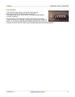
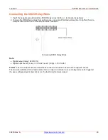
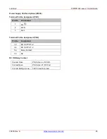
Connecting the DI/DO Relay Wires
1. Insert the negative (ground)/positive DI/DO Relay wires into the +/- terminals, respectively.
2. To keep the DI/DO Relay wires from pulling loose, use a small flat-blade screwdriver to tighten the wire-
clamp screws on the front of the terminal block connector.
Connecting DI/DO Relay Wires
Note
:
•
Digital output (relay): 24VDC/1A
•
Digital input: level 0 (Low) -> 0V to 6V, level 1 (High) -> 10V to 24V
FAULT
: The two contacts of the terminal block connector are used to detect user-configured events.
The two wires attached to the fault contacts form an open circuit when a user-configured event is triggered.
If a user-configured event does not occur, the fault circuit remains closed.


