2: Description and Specifications
Micro125 Embedded Device Server Integration Guide
9
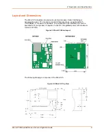
The following drawing shows the connector end view of the board with the LEDs and
RJ45 connector installed. The drawing on the right shows the dimensions for CON1 (DIL
2 x 6).
Figure 2-3 Micro125 Connector End View
Connectors
The Micro125 has four connectors: a TTL serial port (CON1), a 10/100Base-T RJ45
Connector (CON2), and/or pins instead of the RJ45 connector (CON3) and LEDs
(CON4).
Figure 2-4 Micro125 Connectors
CON1
(TTL)
1
11
2
12
CON2
(RJ45)
CON3
1
2
3
4
1
2
7
8
S1
CON4
(LEDs)
The Micro125 that comes with the integration kit is factory configured. When ordering the
Micro125 for production use, each connector can be specified as follows:
Pins on/off the board and top/bottom (
Figure 2-2
and
Figure 2-3
)
LEDs on/off the board
RJ45 on/off the board
Contact Lantronix for information about ordering the Micro125 with customized connector
configurations.
The Embedded Integration Kit (part number Micro-Kit) includes the Micro125 embedded
device server. Refer to the following table for a listing of its pinouts.


