2: Description and Specifications
Micro125 Embedded Device Server Integration Guide
10
Table 2-1 Micro125 Connector Pinouts
CON1
TTL Serial Port
(DIL 2 x 6 Pins)
CON2
10/100Base-T
(RJ45) Connector
CON3 (2 x 2 Pins
in place of RJ45)
CON4 (2 x 4 Pins in place
of LEDs)
Pin
Signal
Pin
Signal
Pin
Signal
Pin
Signal
1
+5VDC
1
Tx+
1
Tx+
1
+3.3 VDC
2
GND
2
Tx-
2
Tx-
2
+3.3 VDC
3
RxA (input)
3
Rx+
3
Rx+
3
LED3
(Diagnostics)1
4
TxA (output)
4
None
2
(tied to Pin
5)
4
Rx-
4
LED1 (Channel 1)
1
5
RTSA (output)
5
None (tied
to Pin 4)
5
+3.3 VDC
6
DTRA (output)
6
Rx-
6
+3.3 VDC
7
CTSA (input)
7
None (tied
to Pin 8)
7
LED2 (Channel 2)
1
8
DCDA (input)
8
None (tied
to Pin 7)
8
LED4 (Link)
1
9
Reserved
10
RESET (pull
low to reset)
Note:
the reset
input is 3.3V
tolerant.
11
RxB (input)
12
TxB (output)
1
Current limiting resistor on board is 220 Ohms.
2
150 Ohms exist between the Pin 4/5 node and the Pin 7/8 node.
A = Port (Channel) 1 B = Port (Channel) 2
Ethernet Interface
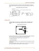
The standard Micro125 ships with an RJ45 10/100Base-T Ethernet connector (CON2). At
the time of ordering, you can specify whether to include this RJ45 connector. You can
use CON3 as an alternative.
Figure 2-5 RJ45 Ethernet Connector
1
8
1 - TX+
2 - TX-
3 - RX+
6 - RX-


