background image

R6S User Manual


50 


Feature 

Options 

Description 

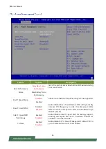
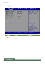
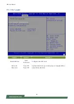
Slot1 Selector 

Wi-Fi 

LTE


Select Which Slot would be used 

Slot2 Selector 

Wi-Fi 

LTE


Select Which Slot would be used 


Содержание R6S

Страница 1: ...1 R6S User Manual Version 1 6 Date of Release 2022 05 04 ...

Страница 2: ...oad Center For certain categories of documents please register for a Lanner Account at Lanner s official website in order to access published documents and downloadable resources In addition to contacting your distributor or sales representative you could visit our Lanner Technical Support to fill in a support ticket to our technical support department This document is copyrighted 2022 All rights ...

Страница 3: ... Huilongguan Town Changping District Beijing 102208 China T 86 010 82795600 F 86 010 62963250 E service ls china com cn USA Lanner Electronics Inc 47790 Westinghouse Drive Fremont CA 94539 T 1 855 852 6637 F 1 510 979 0689 E sales_us lannerinc com Canada Lanner Electronics Canada Ltd 3160A Orlando Drive Mississauga ON L4V 1R5 Canada T 1 877 813 2132 F 1 905 362 2369 E sales_ca lannerinc com Europe...

Страница 4: ...nterference by one or more of the following measures Reorient or relocate the receiving antenna Increase the separation between the equipment and receiver Connect the equipment into an outlet on a circuit different from that to which the receiver is connected Consult the dealer or an experienced radio TV technician for help Any changes or modifications not expressly approved by the party responsib...

Страница 5: ...aillez pas seul si des conditions dangereuses sont présentes Ne considérez jamais que l alimentation est coupée d un circuit vérifiez toujours le circuit Cet appareil génère utilise et émet une énergie radiofréquence et s il n est pas installé et utilisé conformément aux instructions des fournisseurs de composants sans fil il risque de provoquer des interférences dans les communications radio Ther...

Страница 6: ...nt causer des pannes totales ou intermittentes Suivez les procédures de prévention d ESD lors du retrait et du remplacement de composants Portez un bracelet anti ESD et veillez à ce qu il soit bien au contact de la peau Si aucun bracelet n est disponible reliez votre corps àla terre en touchant la partie métallique du châssis Vérifiez régulièrement la valeur de résistance du bracelet antistatique ...

Страница 7: ...Proper grounding grounding is very important to protect the equipment against the harmful effects of external noise and to reduce the risk of electrocution in the event of a lightning strike To uninstall the equipment disconnect the ground wire after turning off the power A ground wire is required and the part connecting the conductor must be greater than 4 mm2 or 10 AWG Avant d allumer l appareil...

Страница 8: ...R6S User Manual 8 ...

Страница 9: ...Processor Certified with EN 50155 EN 50121 3 2 EN 50121 4 EN 50125 3 and EN45545 standard 10x rugged PoE ports with M12 connectors Support full size mini PCIe M 2 sockets for LTE Wi Fi Wide range operating temperature from 40 to 70 C Onboard GPS receiver module and G sensor 1x Removable 2 5 drive bay for 2x 2 5 storage HDD SSD is not included Built in CAN bus port Rich I O 2x USB 2 0 2x USB 3 0 2 ...

Страница 10: ...ol to MCU USB A SKU 3x USB 2 0 Type A 2x USB 3 0 Type A B C SKU 2x USB 2 0 Type A 2x USB 3 0 Type A Antenna A SKU SMA antenna hole x6 includes GPS GLONASS x1 B C SKU SMA antenna hole x12 includes GPS GLONASS x1 Expansion Interface PCIe USB A SKU Full size Mini PCIe Socket x2 with dual SIM card readers on each B C SKU Full size Mini PCIe Socket x1 M 2 x4 with SIM card readers on each Cooling Proces...

Страница 11: ...R6S User Manual 11 Certification EMC FCC CE Class A RoHS Safety E 13 include ISO 7637 2 Certified IP rated 50 MIL STD 810G EN 50155 EN 50121 3 2 EN 50121 4 EN 50125 3 and EN 45545 ...

Страница 12: ... 0 Port 2x USB 2 0 Type A F4 GbE Port 1x RJ45 port with LED indicators F5 SIM Cover A SKU 2x Dual SIM card socket B C SKU 5x Single SIM card socket F6 Storage Lock Lock for removable 2 5 storage caddy F7 Antenna Port LTE Antenna Wi Fi Antenna F8 Storage Bay 2x SATA interface storage bays to support removable 2 5 HDD SSD drive F9 SD Card SD Card socket ...

Страница 13: ...Output 1x M12 A coded 5 pin for DC 12V power output Pin Signals Pin Signals 1 12V_Output 2 FORWARD 3 SPEED 4 12V_GND 5 GPS GND R4 DVI D Port 1x DVI D Connector R5 VGA Port 1x VGA DB15 Connector R6 COM Port 2x DB9 Male Connector for RS232 422 485 Pin Signals Pin Signals 1_down COM1_C_DCD_TN 2_up COM1_C_RXD_TP 3_down COM1_C_TXD_RP 4_up COM1_C_DTR_RN 5_down GND_COM 6_up COM1_C_DSR 7_down COM1_C_RTS 8...

Страница 14: ...6 DI_4 25 DO_3 8 V_CAR BAT 17 GND_CAN 26 DO_4 9 DI_COM 18 DI_6 R8 Audio Port 1x Realtek ALC886 GR supports external Audio I O for MIC in Line out with L R channels via 9 pin female connector Pin Signals Pin Signals 1 MIC_IN_R 2 GND_AUD 3 X 4 GND_AUD 5 AMPOUT_R 6 MIC_IN_L 7 GND_AUD 8 GND_AUD 9 AMPOUT_L R9 Antenna Port GPS GLONASS default 1x 3 GNSS GPS Galileo GLONASS BeiDou antenna G sensor no ante...

Страница 15: ...vel Pin Signals Pin Signals 1 GND 2 DC_VIN 3 MCU_PG 4 IGN_IN 5 PE CHASSIS GND R3 COM 1 Port Console Pin Signals Pin Signals 1 COM1_C_DCD_TN 2 COM1_C_RXD_TP 3 COM1_C_TXD_RP 4 COM1_C_DTR_RN 5 COM1_2_GND 6 COM1_C_DSR 7 COM1_C_RTS 8 COM1_C_CTS 9 COM1_C_RI R4 COM 2 Port Pin Signals Pin Signals 1 COM2_C_DCD_TN 2 COM2_C_RXD_TP 3 COM2_C_TXD_RP 4 COM2_C_DTR_RN 5 COM2_2_GND 6 COM2_C_DSR 7 COM2_C_RTS 8 COM2_...

Страница 16: ... GPIO CAN Bus Pin Signals Pin Signals Pin Signals 1 FORWARD_CONN 10 SPEED_CONN 19 DO_5 2 DI_0 11 DGIN_0 20 12V_GND 3 DI_1 12 GND_GPS 21 12V_GND 4 DI_2 13 X 22 DO_0 5 DI_3 14 DO_6 23 DO_1 6 DIO_GND 15 DGIN_1 24 DO_2 7 X 16 DI_4 25 DO_3 8 X 17 DI_5 26 DO_4 9 DI_COMMON 18 DI_6 DO_5 R9 Audio Port 1x Realtek ALC886 GR supports external audio I O for Mic in Line out with L R channels via 9 pin Female Co...

Страница 17: ...R6S User Manual 17 ...

Страница 18: ...R6S User Manual 18 Front View ...

Страница 19: ...R6S User Manual 19 Rear View ...

Страница 20: ...R6S User Manual 20 Front View ...

Страница 21: ...R6S User Manual 21 Rear View ...

Страница 22: ...R6S User Manual 22 Front View ...

Страница 23: ...R6S User Manual 23 Rear View ...

Страница 24: ...R6S User Manual 24 ...

Страница 25: ...R6S User Manual 25 B SKU C SKU ...

Страница 26: ...R6S User Manual 26 ...

Страница 27: ...R6S User Manual 27 ...

Страница 28: ...R6S User Manual 28 ...

Страница 29: ...gnals 1 GND 2 DC_IN 3 GND 4 IGN_IN 5 CHASSIS GND PW2 DC_OUT Pin Signals 1 IGN_OUT 2 MCU_PG 3 DC 54V Output 4 GND 5 CHASSIS GND RPB6SB1 CN1 Pin Signals 1 EXT_TXD_R 2 GND_PSEDCIN_1 3 EXT_RXD_R JMCU1 Pin Signals 1 IGN3V3_SB 2 PIO_1 3 GND_PSEDCIN_1 ...

Страница 30: ...PTER 2 HARDWARE SETUP To install the hard disk 1 Loosen the two hand screws that secure the hard disk tray 2 Pull out the tray as shown in the picture below 3 Remove the screws shown in the picture in order to open the tray ...

Страница 31: ...R6S User Manual 31 4 Install the disk onto the tray and connect the SATA cable Then repeat the same steps to install the other disk 5 Lock the disk tray into the system chassis ...

Страница 32: ...p the system 2 Pressing the Tab or Del key immediately allows you to enter the Setup utility and then you will be directed to the BIOS main screen The instructions for BIOS navigations are as below Control Keys Description select a setup screen for instance Main Advanced IntelRCSetup Security Boot and Save Exit select an item option on a setup screen Enter select an item option or enter a sub menu...

Страница 33: ...nel version CRB code base X64 Compliancy UEFI version PI version Project Version BIOS release version Build Date and Time MM DD YYYY Access Level Administrator User System Date To set the Date use Tab to switch between Date elements Default Range of Year 2005 2099 Default Range of Month 1 12 Days dependent on Month System Time To set the Date use Tab to switch between Date elements ...

Страница 34: ...R6S User Manual 34 Select the Advanced menu item from the BIOS setup screen to enter the Advanced setup screen Users can select any of the items in the left frame of the screen ...

Страница 35: ...R6S User Manual 35 ...

Страница 36: ...ed Enabled To turn on off the MLC streamer prefetcher Adjacent Cache Line Prefetch Disabled Enabled To turn on off prefetching of adjacent cache lines Intel VMX Virtualization Technology Disabled Enabled When enabled a VMM can utilize the additional hardware capabilities provided by Vanderpool Technology Active Processor Cores ALL 1 Number of cores to enable in each processor package Hyper Threadi...

Страница 37: ...eck MonitorMWait Disabled Enabled Enable Disable MonitorMWait Intel Trusted Execution Technology Disabled Enabled Enables utilization of additional hardware capabilities provided by Intel Trusted Execution Technology Changes require a full power cycle to take effect Alias Check Request Disabled Enabled Enables Txt Alias Checking capability Changes require full Txt capability before it will take ef...

Страница 38: ...R6S User Manual 38 ...

Страница 39: ...lt RTH Disabled Enabled Enable Disable Race To Halt feature RTH will dynamically increase CPU frequency in order to enter pkg C State faster to reduce overall power RTH is controlled through MSR 1FC bit 20 Intel Speed Shift Technology Enabled Disabled Enable Disable Intel Speed Shift Technology support Enabling will expose the CPPC v2 interface to allow for hardware controlled P states C states En...

Страница 40: ...R6S User Manual 40 Feature Options Description ME State Disabled Enabled When Disabled ME will put into ME Temporarily Disabled Mode ...

Страница 41: ...R6S User Manual 41 Feature Options Description Me FW Image Re Flash Disabled Enable Enable Disable Me FW Image Re Flash function ...

Страница 42: ...R6S User Manual 42 ...

Страница 43: ...ons Description Serial Port Disabled Enabled Enable or Disable Serial Port COM Device Settings NA IO 3F8h IRQ 4 COM1 Mode RS232 RS485 RS422 COM RS 422 485 Support COM1 Termination Disabled Enabled COM RS 422 485 Receiver Termination ...

Страница 44: ...ons Description Serial Port Disabled Enabled Enable or Disable Serial Port COM Device Settings NA IO 2F8h IRQ 3 COM2 Mode RS232 RS485 RS422 COM RS 422 485 Support COM2 Termination Disabled Enabled COM RS 422 485 Receiver Termination ...

Страница 45: ...R6S User Manual 45 Feature Options Description Serial Port Disabled Enabled Enable or Disable Serial Port COM Device Settings NA IO 3E8h IRQ 5 ...

Страница 46: ...ons Description Serial Port Disabled Enabled Enable or Disable Serial Port COM Device Settings NA IO 2E8h IRQ 11 COM4 Mode RS232 RS485 RS422 COM RS 422 485 Support COM4 Termination Disabled Enabled COM RS 422 485 Receiver Termination ...

Страница 47: ...ons Description Serial Port Disabled Enabled Enable or Disable Serial Port COM Device Settings NA IO 2F0h IRQ 7 COM5 Mode RS232 RS485 RS422 COM RS 422 485 Support COM5 Termination Disabled Enabled COM RS 422 485 Receiver Termination ...

Страница 48: ...R6S User Manual 48 Feature Options Description Serial Port Disabled Enabled Enable or Disable Serial Port COM Device Settings NA IO 2E0h IRQ 10 ...

Страница 49: ...R6S User Manual 49 ...

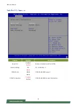
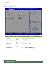
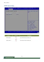
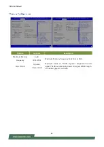
Страница 50: ...R6S User Manual 50 Feature Options Description Slot1 Selector Wi Fi LTE Select Which Slot would be used Slot2 Selector Wi Fi LTE Select Which Slot would be used ...

Страница 51: ...R6S User Manual 51 Feature Options Description Status LED Dark Green Red Configuration Status LED ...

Страница 52: ...R6S User Manual 52 Feature Options Description COM1 Console Redirection Disabled Enabled Console Redirection Enable or Disable ...

Страница 53: ...II char set Bits per second 9600 19200 38400 57600 115200 Selects serial port transmission speed The speed must be matched on the other side Long or noisy lines may require lower speeds Data Bits 7 8 Data Bits Parity None Even Odd Mark Space A parity bit can be sent with the data bits to detect some transmission errors Stop Bits 1 2 Indicates the end of a serial data packet Flow Control None Flow ...

Страница 54: ...upport for ANSI VT100 terminals Recorder Mode Disabled Enabled With this mode enabled only text will be sent This is to capture Terminal data Resolution 100x31 Disabled Enabled Enables or disables extended terminal resolution Putty KeyPad VT100 LINUX XTERM86 SCO ESCN VT400 Selects FunctionKey and KeyPad on Putty ...

Страница 55: ...x24 80x25 On Legacy OS the Number of Rows and Columns supported redirection Redirection After BIOS Post Always Enable Bootloader When Bootloader is selected Legacy Console Redirection is disabled before booting to legacy OS When Always Enable is selected then Legacy Console Redirection is enabled for legacy OS Default setting for this option is set to Always Enable ...

Страница 56: ...R6S User Manual 56 ...

Страница 57: ...r Manual 57 Feature Options Description Above 4G Decoding Disabled Enabled Globally Enables or Disables 64bit capable devices to be decoded in above 4G address space only if System supports 64bit PCI decoding ...

Страница 58: ...R6S User Manual 58 Feature Options Description Network Stack Disabled Enabled Enables or disables UEFI Network Stack ...

Страница 59: ...ls the execution of UEFI and Legacy PXE OpROM Storage Do Not Launch UEFI Legacy Controls the execution of UEFI and Legacy Storage OpROM Video Do Not Launch UEFI Legacy Controls the execution of UEFI and Legacy Video OpROM Other PCI Device Do Not Launch UEFI Legacy Determines OpROM execution policy for devices other than Network Storage or Video ...

Страница 60: ...R6S User Manual 60 ...

Страница 61: ...bled Auto Enables Legacy USB support Auto option disables legacy support if no USB devices are connected Disabled option will keep USB devices available only for EFI applications USB Mass Storage Driver Support Disabled Enabled Enables or disables USB Mass Storage Driver Support ...

Страница 62: ...R6S User Manual 62 Select the Chipset menu item from the BIOS setup screen to enter the Chipset setup screen Users can select any of the items in the left frame of the screen ...

Страница 63: ...d Enabled VT d capability Above 4GB MMIO BIOS assignment Disabled Enabled Enable Disable above 4GB MemoryMappedIO BIOS assignment This is enabled automatically when Aperture Size is set to 2048MB Z2APIC Opt Out Disabled Enabled Enable Disable X2APIC_OPT_OUT bit ...

Страница 64: ... Maximum Memory Frequency Auto 1067 3733 Maximum Memory Frequency Selections in MHz Max TOLUD Dynamic 1GB 3 5GB Maximum Value of TOLUD Dynamic assignment would adjust TOLUD automatically based on largest MMIO length of installed graphic controller ...

Страница 65: ...l 65 Feature Options Description Serial IRQ Mode Quiet Continuous Configure Serial IRQ mode Restore AC Power Loss Power ON Power OFF Specify what state to go to when power is re applied after a power failure G3 state ...

Страница 66: ...R6S User Manual 66 ...

Страница 67: ...inks to 0s State AUTO BIOS auto configure DISABLE Disabled ASPM Advanced Error Reporting Disabled Enabled Advanced Error Reporting Enable Disable PCIe Speed Auto Gen1 Gen2 Gen3 Configure PCIe Speed Detect Timeout 0 The number of milliseconds reference code will wait for link to exit Detect state for enabled ports before assuming there is no device and potentially disabling the port ...

Страница 68: ...all links to L0s State AUTO BIOS auto configure DISABLE Disabled ASPM Advanced Error Reporting Disabled Enabled Advanced Error Reporting Enable Disable PCIe Speed Auto Gen1 Gen2 Gen3 Configure PCIe Speed Detect Timeout 0 The number of milliseconds reference code will wait for link to exit Detect state for enabled ports before assuming there is no device and potentially disabling the port ...

Страница 69: ...all links to L0s State AUTO BIOS auto configure DISABLE Disabled ASPM Advanced Error Reporting Disabled Enabled Advanced Error Reporting Enable Disable PCIe Speed Auto Gen1 Gen2 Gen3 Configure PCIe Speed Detect Timeout 0 The number of milliseconds reference code will wait for link to exit Detect state for enabled ports before assuming there is no device and potentially disabling the port ...

Страница 70: ...all links to L0s State AUTO BIOS auto configure DISABLE Disabled ASPM Advanced Error Reporting Disabled Enabled Advanced Error Reporting Enable Disable PCIe Speed Auto Gen1 Gen2 Gen3 Configure PCIe Speed Detect Timeout 0 The number of milliseconds reference code will wait for link to exit Detect state for enabled ports before assuming there is no device and potentially disabling the port ...

Страница 71: ...all links to L0s State AUTO BIOS auto configure DISABLE Disabled ASPM Advanced Error Reporting Disabled Enabled Advanced Error Reporting Enable Disable PCIe Speed Auto Gen1 Gen2 Gen3 Configure PCIe Speed Detect Timeout 0 The number of milliseconds reference code will wait for link to exit Detect state for enabled ports before assuming there is no device and potentially disabling the port ...

Страница 72: ...all links to L0s State AUTO BIOS auto configure DISABLE Disabled ASPM Advanced Error Reporting Disabled Enabled Advanced Error Reporting Enable Disable PCIe Speed Auto Gen1 Gen2 Gen3 Configure PCIe Speed Detect Timeout 0 The number of milliseconds reference code will wait for link to exit Detect state for enabled ports before assuming there is no device and potentially disabling the port ...

Страница 73: ...R6S User Manual 73 ...

Страница 74: ...e or Disable SATA Port Hot Plug Disabled Enabled Designates this port as Hot Pluggable Spin Up Device Disabled Enabled If enabled for any of ports Staggered Spin Up with be performed and only the drivees which have this option enabled will spin up at boot Otherwise all drives spin up at boot SATA Device Type Hard Disk Drive Solid State Drive Identify the SATA port is connected to Solid State Drive...

Страница 75: ...scription RTC Lock Disabled Enabled Enable will lock bytes 38h 3Fh in the lower upper 128 byte bank of RTC RAM BIOS Lock Disabled Enabled Enable Disable the PCH BIOS Lock Enable feature Required to enabled to ensure SMM protection of flash ...

Страница 76: ...left frame of the screen Feature Options Administrator Password If ONLY the Administrator s password is set it only limits access to Setup and is only asked for when entering Setup User Password If ONLY the User s password is set it serves as a power on password and must be entered to boot or enter Setup In Setup the user will have Administrator rights ...

Страница 77: ... activated when Platform Key PK is enrolled System mode is User Deployed and CSM function is disabled Secure Boot Customization Standard Custom Customizable Secure Boot mode In custom mode Secure Boot Policy variables can be configured by a physically present user without full authentication ...

Страница 78: ...ystem in Setup Mode Restore Factory Keys None Force System to User Mode Configure NVRAM to contain OEM defined factory default Secure Boot keys Enroll Ffi Image None Allows the image to run in Secure Boot mode Enroll SHA256 hash of the binary into Authorized Signature Database db Restore DB defaults None Restore DB variable to factory defaults ...

Страница 79: ...Timeout 5 The number of seconds to wait for setup activation key 65535 means indefinite waiting Bootup NumLock State ON OFF Select the keyboard NumLock state Quiet Boot Disabled Enabled Enables or disables Quiet Boot option Boot mode select LEGACY UEFI DUAL Select boot mode for Legacy or UEFI Choose boot priority from boot option group Choose specifies boot device priority sequence from available ...

Страница 80: ...p screen Users can select any of the items in the left frame of the screen Select this option to quit Setup without saving any modifications to the system configuration The following window will appear after the Discard Changes and Exit option is selected Select Yes to Discard changes and Exit Setup ...

Страница 81: ...system configuration parameters to take effect The following window will appear after selecting the Save Changes and Reset option is selected Select Yes to Save Changes and reset Restore default values for all setup options Select Yes to load Optimized defaults PS The items under Boot Override were not same with image It should depend on devices connect on system ...

Страница 82: ...ows LED COLOR LED ACTION DESCRIPTION Power Green Steady System is powered ON OFF N A System is powered OFF Status Green Steady System is Active Red Steady System Error OFF N A System is powered OFF Note Status bi color LED controlled by GPIO Storage Amber Blinking Storage HDD SSD Active OFF N A No Data Access ...

Страница 83: ...efinition and illustration below to connect the vehicle battery and ignition ACC to the in vehicle system through the 5 pin M12 male connector marked as DC Input on the system through the right pin contact In a typical in vehicle computing solution this system usually acts as a PSE Power Sourcing Equipment to power up connected PoE devices for which you should ensure a minimum of 48V DC power supp...

Страница 84: ...gnition on Trigger Signal PIN 2 MCU_PG MCU Power_good detect pin Isolated PIN 3 DC 54V Output 54V Output PIN 4 GND Secondary Ground S_G for NVR PIN 5 PE CHASSIS GND Chassis Ground System NVR Description M12 K Code Male DC Input PIN Description PIN 1 GND Signal Ground PIN 2 DC_IN DC Power Input from DC converter 52V PIN 3 MCU_PG System Power Good Status without isolated because EMI solution PIN 4 I...

Страница 85: ...lt 8500mV GET INPUT_VOLTAGE_MIN PowerOn Delay Sec SET POWERON_DELAY 4 default 4S GET POWERON_DELAY PowerOff Delay Sec SET SHUTDOWN_DELAY 4 default 4S GET SHUTDOWN_DELAY Input Voltage GET INPUT_VOLTAGE Wakeup DI1 SET WAKEUP_ENABLE 7 default 1 DI1 2 Reserved 4 Reserved Device ID GET DEVICE_ID R6S_N Firmware Version GET VERSION 0 06B Digital Out LTE on off SET DIGITAL_OUT 31 default Digial In GET DIG...

Страница 86: ...R6S User Manual 86 Example ...

Страница 87: ...R6S User Manual 87 ...

Страница 88: ...e following conditions are excluded from this warranty Improper or inadequate maintenance by the customer Unauthorized modification misuse or reversed engineering of the product Operation outside of the environmental specifications for the product Requesting an RMA 1 To obtain an RMA number simply fill out and fax the RMA Request Form to your supplier 2 The customer is required to fill out the pro...

Страница 89: ...R6S User Manual 89 When requesting RMA service please fill out the following form Without this form enclosed your RMA cannot be processed ...

Отзывы: