background image


NCA-5530


User Manual


Version: 1.1 

Date of Release:2021-11-17 

Network Appliance Platforms


Содержание NCA-5530

Страница 1: ...NCA 5530 User Manual Version 1 1 Date of Release 2021 11 17 Network Appliance Platforms...

Страница 2: ...ent font types and icons in order to make selected text more transparent and explicable to users Please note that this document contains the following conventions Example Convention Usage iptables F M...

Страница 3: ...e support is offered to our customers in the United States and Canada Toll free customer service number 1 855 852 6637 This document is copyrighted 2021 by Lanner Electronics Inc All rights are reserv...

Страница 4: ...Town Changping District Beijing 102208 China T 86 010 82795600 F 86 010 62963250 E service ls china com cn USA Lanner Electronics Inc 47790 Westinghouse Drive Fremont CA 94539 T 1 855 852 6637 F 1 510...

Страница 5: ...interference by one or more of the following measures Reorient or relocate the receiving antenna Increase the separation between the equipment and receiver Connect the equipment into an outlet on a c...

Страница 6: ...instructions des fournisseurs de composants sans fil il risque de provoquer des interf rences dans les communications radio There is risk of explosion if the battery is replaced by an incorrect type...

Страница 7: ...used in The installation of this product must be performed by trained specialists otherwise a non specialist might create the risk of the system s falling to the ground or other damages Lanner Electro...

Страница 8: ...aire plus de 4 mm2 ou 10 AWG Connect the grounding cable to the ground The protection device for the DC power source must provide 30 A current This protection device must be connected to the power sou...

Страница 9: ...ening the Chassis 27 Installing the CPU 28 Installing the System Memory 34 Installing TPM Module Optional 37 Installing the M 2 SSD memory card Optional 38 Installing the Disk Drive s 39 Installing th...

Страница 10: ...0 Platform Configuration 75 Socket Configuration 81 Server Mgmt 95 Security 100 Boot Menu 103 Save and Exit Menu 104 Why Dual BIOS 112 Addressing BIOS Start up Failure with Dual BIOS 113 Warranty Poli...

Страница 11: ...kit with screws 1x RJ45 Console cable 1x RJ45 LAN Cable Grey 8x HDD screws 1x Processor Carrier 1x CPU Heatsink Model No Description NCS2 LCM6210A LCM Module for NCS2 By ODM OEM IAC TPM04A TPM Module...

Страница 12: ...n IAC AST2500E install OPMA slot Socket type I O Interface Reset Button 1x Reset Button Default software reset control by GPIO LED Power Status Storage refer to Appendix A Power Button 1x ATX Power Sw...

Страница 13: ...al 13 Package Dimensions Size WxDxH 739 x 215 x 582 mm Weight 18 5kg Power Type Watts 550W AC 1 1 Redundant PSU Input AC 100V 240V 47 63Hz Approvals and Compliance RoHS Directive EU 2015 863 CE FCC Cl...

Страница 14: ...F2 LED Indicators F3 USB Ports 2x USB 3 0 F4 RJ45 Port 1x RJ45 port F5 Console Port 1x Console port F6 NIC Module Slot 4x or 2x NCS2 Slim Type Module By SKU or 1x or 2x N2S NIC Module By Project Syste...

Страница 15: ...1 1 Redundant CRPS Power Supply R2 Fans 5x or 4x Hot swappable Cooling Fans By SKU R3 Power Switch 1x Power Switch I O Button R4 Alarm Reset 1x Alarm Reset Button R5 ESD Jack 1x ESD screw hole R6 Gro...

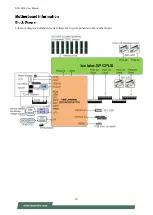
Страница 16: ...NCA 5530 User Manual 16 The block diagram indicates how data flows among components on the motherboard...

Страница 17: ...ence of the pin assignments and the internal connectors JSATAPW1 JSATAPW2 JFAN5 JFAN4 JFAN3 OPMA1 JMERCVR1 JOPEN1 JPMB1 JIOB1 JCLRPAS1 JCOM2 JUSB1 JPCIESL1 JPCIESL2 JSLOT3 JNGFF3 JRAID CON1 JGP1 JLPC_...

Страница 18: ...ain feature can be enabled or disabled While changing the jumpers make sure your system is turned off JUSB1 USB2 0 Pin No Description Pin No Description 1 P5V_USB2 2 P5V_USB2 3 USB20_L_N3 4 USB20_L_N4...

Страница 19: ...1 Pin No Description Pin No Description 1 SPI_HD1 2 SPI_CS1 3 SPI_CS0 4 P3V3_SPI_PCH_AUX 5 SPI_MISO_TPM 6 HEADER_SPI_PCH_IO3 7 8 SPI_CLK_TPM 9 GND 10 SPI_MOSI_TPM 11 IRQ_TPM_SPI _R 12 13 SPI_TPM_CS0 1...

Страница 20: ...ription 1 FM_INTRUDER 2 GND JFAN1 5 FAN Connector Pin No Description 1 Ground 2 P12V 3 FAN_TECH_IN Sense 2 4 FAN_TECH_IN Sense 1 5 FAN_PWM_OUT SW1 Front Panel RST Button SW2 Power ON Button JSATA1 4 S...

Страница 21: ...4 24 Pin Power Connector Pin No Description Pin No Description 2 12VSB 1 GND 4 5V 3 GND 6 12V 5 GND 8 12V 7 GND 10 12V 9 GND 12 12V 11 GND 14 12V 13 GND 16 12V 15 GND 18 12V 17 GND 20 12V 19 GND 22 3V...

Страница 22: ...that they become SHORT To make the pins setting OPEN simply remove the jumper cap 2 pin Header 3 pin Header 4 pin Header Open Short Open 1 2 Jumped Open 1 2 Jumped JFOR_PWRON1 1 2 1 2 Normal Operatio...

Страница 23: ...1 2 FM_ME_RCVR_N 3 GND JCMOS1 1 2 1 2 Normal 2 3 Clear CMOS Pin No Description 1 VRTC 2 PCH_RTCRST 3 PD_PCH_RTCRST JPMB1 PMBUS Pin No Description Pin No Description 1 P3V3_SB 2 3 ATX_PSON 4 GND 5 ATX...

Страница 24: ...ription 1 P3V3_AUX 2 DUAL_BIOS_DIS 3 GND JCOM2 The power board layout shows the connectors and jumpers on the board Refer to the following picture as a reference of the pin assignments and the interna...

Страница 25: ...S_CLK 7 PMBUS_DAT 8 PMBUS_ALERT JATXP5V 4 pin Power Connector Pin No Description Pin No Description 1 GND 2 P5V 3 GND 4 P5V DC1 3 4 pin Power Connector Pin No Description Pin No Description 1 P12V 2 P...

Страница 26: ...er Connector Pin No Description Pin No Description 2 12Vsb 1 GND 4 5V 3 GND 6 12V 5 GND 8 12V 7 GND 10 12V 9 GND 12 12V 11 GND 14 12V 13 GND 16 12V 15 GND 18 12V 17 GND 20 12V 19 GND 22 3V 21 GND 24 3...

Страница 27: ...age to the system please remove all power connections to shut down the device completely and wear ESD protection gloves when handling the installation steps 1 Loosen the two 2 thumb screws on the rear...

Страница 28: ...The images of tools shown in this document are merely for reference the actual tools you use might differ Tool Description Torque screwdriver T 30 Torx Bit Set to 8in lb for tightening the nuts which...

Страница 29: ...correctly Socket Cover This cover is used to protect the package land surface of the processor from contamination To remove it from the processor grasp the holding features with your thumb and your i...

Страница 30: ...the locking tabs Note During assembly it is essential to have 1 PIN1 on the processor carrier aligned with the processor and 2 the alignment features on the top and the bottom of the processor aligne...

Страница 31: ...the PIN1 end of the heatsink over the processor carrier to engage the two locking tabs near the corners Then push the other end down to engage the locking tabs at the remaining corners You might hear...

Страница 32: ...r sufficient lighting to ensure there is no contamination or damage prior to the PHM installation 2 Set each anti tilt wire to inward or unlocked position on the heatsink 3 Lift up the PHM Turn the PH...

Страница 33: ...ire to outward or locked position 6 Check the anti tilt wires are in locked position and have engaged the anti tilt flanges on the bolster plate 7 Use a torque driver with a T 30 Torx bit to tighten t...

Страница 34: ...lines Please do follow the memory module installation instructions to install the DIMM and make sure the DIMM population guidelines are met Each CPU requires at least 1 memory module to boot and run f...

Страница 35: ...ls must be populated with same total capacity per channel if populate B F D H channels must be populated with same total capacity if populated SNC2 configuration requires full asymmetry together with...

Страница 36: ...1 Power off the system and open the chassis cover 2 Pull open the DIMM slot latches 3 Align the notch of the DIMM module with the socket key in the slot 4 Insert the module into the slot until it is...

Страница 37: ...provides one TPM slot Follow the procedures below for installing a TPM module 1 Power off the system and open the chassis cover 2 Locate the TPM slot on the motherboard 3 Insert the TPM module into th...

Страница 38: ...1 Power off the system and open the chassis cover 2 Locate the M 2 slot on the motherboard 3 Align the notch of the M 2 memory card with the socket key in the pin slot 4 Insert the M 2 memory card pin...

Страница 39: ...The following will discuss disk drive installation procedures based on their HDD SSD designs 1 Power off the system and open the chassis cover 2 Locate the 2 5 disk bay 3 Loosen the three 3 screws th...

Страница 40: ...towards the inside the system 5 Screw in the hard disk on both sides two 2 screws on each side 6 Install the tray back to the original position on the motherboard and secure with the three 3 screws 7...

Страница 41: ...le package consists of 1x LCM Panel 1x LCM connector cable 2x screws 2 Power off the system and open the chassis cover 3 On the front panel select the first module slot for LCM module placement 4 Loos...

Страница 42: ...stall the LCM module into the module slot 7 Insert the connector cable into the connector pin 8 Secure the LCM module using the two 2 screws Close the top cover of the system The LCM module has been s...

Страница 43: ...ation 1 Power off the system and open the chassis cover 2 On the front panel select a NIC Ethernet module slot 3 Rotate clockwise and loosen the two 2 lock screws and remove the door 4 Locate the sock...

Страница 44: ...NCA 5530 User Manual 44 5 Insert the NIC module Module shown in the image is for reference only 6 Once the module is firmly seated rotate counter clockwise and tighten the two 2 lock screws 6 5...

Страница 45: ...wer off the system and open the chassis cover 2 Locate the IPMI socket on the motherboard 3 Align the notch of the IPMI card with the socket key in the slot 4 Insert at 30 degrees into the socket unti...

Страница 46: ...cooling fan just reverse the steps to install the fan back onto the enclosure and the system 1 On the rear panel loosen the lock screw of the fan you would like to replace 2 Hold onto the lock screw...

Страница 47: ...s only 550W PSU Please prepare the power supply units matching this capacity 1 On the rear panel locate the power supply units and disconnect the power cords 2 Hold the handle and pull out the origina...

Страница 48: ...ets The Ear Brackets come with six screws as shown below Take an ear bracket align the holes on it with those on the side of the system and lock it onto the system with the three 3 provided screws Do...

Страница 49: ...ket from the channel locate and push the Release Tab on the rail bracket while sliding it out 4 Align the rail bracket to the side of the chassis and make sure the screw holes are matched and then sec...

Страница 50: ...tion slide the rail to aim and engage the bolts on the rail s rear end with the two 2 available holes on the post and the rail assembly will click into place 3 Repeat Steps 1 2 to install the other ra...

Страница 51: ...about halfway Press down the metal clips on bother inner channels and push them further into the cabinet 4 To have the chassis completely inserted into the rack pull and hold the Rail Lock tab on bot...

Страница 52: ...rol Keys Description select a setup screen for instance Main Advanced Platform Configuration Socket Configuration Server Mgmt Security Boot and Save Exit select an item option on a setup screen Enter...

Страница 53: ...ode base X64 Compliancy UEFI version PI version BIOS Version BIOS release version Build Date and Time MM DD YYYY Access Level Administrator User Memory Information Total Memory by case System Date To...

Страница 54: ...NCA 5530 User Manual 54 Select the Advanced menu item from the BIOS setup screen to enter the Advanced setup screen Users can select any of the items in the left frame of the screen...

Страница 55: ...Options Description Security Device Support Enabled Disabled Enables or disables BIOS support for security device By disabling this function OS will not show Security Device TCG EFI protocol and INT1A...

Страница 56: ...rity Device NOTE Your computer will reboot during restart in order to change State of the Device Pending operation None TPM Clear Schedules an Operation for the Security Device NOTE Your computer will...

Страница 57: ...NCA 5530 User Manual 57...

Страница 58: ...Platform Hierarchy Storage Hierarchy Enabled Disabled Enables or disables Storage Hierarchy Endorsement Hierarchy Enabled Disabled Enables or disables Endorsement Hierarchy TPM2 0 UEFI Spec Version TC...

Страница 59: ...NCA 5530 User Manual 59...

Страница 60: ...NCA 5530 User Manual 60 Feature Options Description Serial Port Enabled Disabled Enables or disables Serial Port 1 Device Settings NA IO 3F8h IRQ 4...

Страница 61: ...NCA 5530 User Manual 61 Feature Options Description Serial Port Enabled Disabled Enables or disables Serial Port 2 Device Settings NA IO 2F8h IRQ 3...

Страница 62: ...NCA 5530 User Manual 62...

Страница 63: ...NCA 5530 User Manual 63 Feature Options Description Smart Fan Mode Configuration None Smart Fan Parameters...

Страница 64: ...e Range 0 127 Target Temperature T3 80 Input Target Temperature Range 0 127 Target Temperature T4 85 Input Target Temperature Range 0 127 Critical Temperature 90 Input Target Temperature Range 0 127 F...

Страница 65: ...NCA 5530 User Manual 65 Feature Options Description COM0 Console Redirection Enabled Disabled Enables or disables Console Redirection...

Страница 66: ...set Bits per second 9600 19200 38400 57600 115200 Selects serial port transmission speed The speed must be matched on the other side Long or noisy lines may require lower speeds Data Bits 7 8 Data Bi...

Страница 67: ...for ANSI VT100 terminals Recorder Mode Disabled Enabled With this mode enabled only text will be sent This is to capture Terminal data Resolution 100x31 Disabled Enabled Enables or disables extended t...

Страница 68: ...tion Resolution 80x24 80x25 On Legacy OS the Number of Rows and Columns supported redirection Redirection After BIOS POST Always Enable BootLoader When Bootloader is selected Legacy Console Redirectio...

Страница 69: ...nabled Enables or disables 64bit capable Devices to be Decoded in Above 4G Address Space Only if System Supports 64 bit PCI Decoding SR IOV Support Disabled Enabled If the system has SR IOV capable PC...

Страница 70: ...e should be claimed by XHCI driver USB Mass Storage Driver Support Enabled Disabled Enables or disables USB Mass Storage Driver Support USB transfer time out 1 sec 5 sec 10 sec 20 sec The time out val...

Страница 71: ...Enables Ipv4 HTTP Boot Support If IPV4 is disabled HTTP boot option will not be created Ipv6 PXE Support Disabled Enabled Enables Ipv6 PXE Boot Support If IPV6 is disabled PXE boot option will not be...

Страница 72: ...trols the execution of UEFI and Legacy PXE OpROM Storage Do Not Launch UEFI Legacy Controls the execution of UEFI and Legacy Storage OpROM Video Do Not Launch UEFI Legacy Controls the execution of UEF...

Страница 73: ...NCA 5530 User Manual 73...

Страница 74: ...NCA 5530 User Manual 74 Feature Options Description Control Legacy PXE Boot from Disabled LAN Select On Board LAN Boot...

Страница 75: ...select any of the items in the left frame of the screen Feature Options Description PCH Configuration None Displays and provides option to change the PCH Settings Server ME Configuration None Configur...

Страница 76: ...s Configuration None PCI Express Configuration settings PCH sSATA Configuration None sSATA devices and settings Restore AC Power Loss Power ON Power Off Last State Select S0 S5 for ACPI state after a...

Страница 77: ...ort Function Swapping Disabled Enabled Enable PCIe root port function swapping feature to dynamically assign function 0 to enabled root port Max Read Request Size MRRS 128B MRRS 256B MRRS 512B MRRS 10...

Страница 78: ...NCA 5530 User Manual 78...

Страница 79: ...this port as Hot Pluggable Configure as eSATA Disabled Enabled Configures port as External SATA eSATA Spin Up Device Disabled Enabled If enabled for any of ports Staggerred Spin Up will be performed a...

Страница 80: ...NCA 5530 User Manual 80...

Страница 81: ...tion None Displays and provides option to change the Processor Settings Memory Configuration None Displays and provides option to change the Memory Settings IIO Configuration None Displays and provide...

Страница 82: ...NCA 5530 User Manual 82...

Страница 83: ...bled Enabled MLC Streamer Prefetcher MSR 1A4h Bit 0 Adjacent Cache Prefetcher Disabled Enabled MLC Spatial Prefetcher MSR 1A4h Bit 1 Extended APIC Disabled Enabled Enables or disables extended APIC su...

Страница 84: ...NCA 5530 User Manual 84 Feature Options Description CPU Socket0 Configuration None None...

Страница 85: ...0 User Manual 85 Feature Options Description Core Disable Bitmap Hex 0 0 Enable all cores FFFFFFFFFFF Disable all cores least one core per CPU must be enabled Disabling all cores is an invalid configu...

Страница 86: ...tions Description Memory Frequency Auto 1200 1333 1400 1600 1800 1866 2000 2133 2200 2400 2600 2666 2800 2933 3000 3200 3400 OvrClk 3466 OvrClk 3600 OvrClk 3733 OvrClk Maximum Memory Frequency Selecti...

Страница 87: ...NCA 5530 User Manual 87 3800 OvrClk 4000 OvrClk 4200 OvrClk 4266 OvrClk 4400 OvrClk 4800 OvrClk Memory Topology None Displays memory topology with Dimm population information...

Страница 88: ...n None IOAT Configuration Intel VT for Directed I O VT d None Intel VT for Directed I O VT d PCI E ASPM Support Global No Per Port L1 Only PCI E ASPM Support Global PCIe Extended Tag Enable Auto No Ye...

Страница 89: ...A Socket 0 Port 2A None Settings related to PCI Express Port 2A Socket 0 Port 2C None Settings related to PCI Express Port 2C Socket 0 Port 4A None Settings related to PCI Express Port 4A Socket 0 Por...

Страница 90: ...Manual 90 Feature Options Description Sck0 IOAT Config None None Disable TPH No Yes TLP Processing Hint disable Prioritize TPH Disabled Enabled Prioritize TPH Relaxed Ordering No Yes Relaxed Ordering...

Страница 91: ...NCA 5530 User Manual 91 Feature Options Description Intel VT for Directed I O VT d No Yes Press Enter to bring up the Intel VT for Directed I O VT d Configuration menu...

Страница 92: ...NCA 5530 User Manual 92 Feature Options Description CPU P State Control None P State Control Configuration Sub Menu include Turbo XE and etc CPU C State Control None CPU C State setting...

Страница 93: ...P States Boot performance mode Max Performance Max Efficient Set by Intel Node Manager Select the performance state that the BIOS will set before OS hand off CPU Flex Ratio Override Disabled Enabled...

Страница 94: ...n CPU C1 auto demotion Disabled Enabled Autonomous Core C State Control CPU C6 report Disabled Enabled Enables or disables CPU C6 ACPI C3 report to OS Enhanced Halt State C1E Disabled Enabled Core C1E...

Страница 95: ...OS starts during AC power ON It takes around 30 seconds to initialize Host to BMC interfaces FRB 2 Timer Enabled Disabled Enables or disables FRB 2 timer POST timer FRB 2 Timer timeout 3 minutes 4 min...

Страница 96: ...length of the OS Boot Watchdog Timer Not available if OS Boot Watchdog Timer is disabled OS Wtd Timer Policy Do Nothing Reset Power Down Power Cycle Configure how the system should respond if the OS...

Страница 97: ...led Enabled Enables or disables all features of System Event Logging during boot Erase SEL NO Yes On next reset Yes On every reset Choose options for erasing SEL When SEL is Full Do Nothing Erase Imme...

Страница 98: ...escription Configuration Address source Unspecified Static DynamicBmcDhcp Select to configure LAN channel parameters statically or dynamically by BIOS or BMC The unspecified option will not modify any...

Страница 99: ...NCA 5530 User Manual 99...

Страница 100: ...left frame of the screen Feature Description Administrator Password If ONLY the Administrator s password is set it only limits access to Setup and is only asked for when entering Setup User Password I...

Страница 101: ...sabled Enabled Secure Boot is activated when Platform Key PK is enrolled System mode is User Deployed and CSM function is disabled Secure Boot Mode Standard Custom Secure Boot mode selector In Custom...

Страница 102: ...lt keys on next re boot only when System in Setup Mode Restore Factory keys None Force System to User Mode Configure NVRAM to contain OEM defined factory default Secure Boot keys Enroll Efi Image None...

Страница 103: ...pecifies boot device priority sequence from available Group device Feature Options Description Setup Prompt Timeout 5 The Number of seconds to wait for setup activation key 65535 means indefinite wait...

Страница 104: ...ect any of the items on the left frame of the screen Discard Changes and Exit Select this option to quit Setup without saving any modifications to the system configuration The following window will ap...

Страница 105: ...new system configuration parameters to take effect The following window will appear after selecting the Save Changes and Reset option is selected Select Yes to Save Changes and reset Restore Defaults...

Страница 106: ...Steady control by GPIO Off Off N A control by GPIO Default or No power on HDD Amber Amber Blinking Blinking indicates HDD activity Include SATA NVME Off Off N A No data access or No power on NC Stand...

Страница 107: ...FF 1G Blinking Data access ON Amber 2 5G Blinking Data access ON Green 1 When cable is plug in and network is linked Both LED will be bright The behavior is as defined 2 Without the Cable plug in the...

Страница 108: ...P 1G Amber SFP 10G Green Link ON Amber ON Green Active Blinking Data access Blinking Data access Non Link OFF OFF 1 When cable is plug in and network is linked Both LED will be bright The behavior is...

Страница 109: ...a access ON Amber 10G Blinking Steady ON Green Non Link OFF OFF 1 When cable is plug in and network is linked Both LED will be bright The behavior is as defined 2 Without the Cable plug in the LED sho...

Страница 110: ...ata access ON Amber Non Link OFF OFF 1 When cable is plug in and network is linked Both LED will be bright The behavior is as defined 2 Without the Cable plug in the LED should be off 3 If LAN Driver...

Страница 111: ...der per port Standard device does NOT include the LED as default If Standard device require LED when Bypass is Enable the LED will be Green Bypass Default Configuration Item Power ON Run Time Power OF...

Страница 112: ...able time and effort but all that work might also be to no avail Eventually users are left with no choice but to ship the board back to the manufacturer Lanner understands this pain and has empowered...

Страница 113: ...d within seconds 25 seconds to 2 minutes depend upon appliance the system will invoke a bootup from the Secondary BIOS automatically restarting the system and launch the operating system To provide in...

Страница 114: ...om Lanner technical support Firmware and Flash Tool BIOS Engineering Spec Before you start make sure you select the correct firmware version correct BIOS Primary or Secondary and go through the instru...

Страница 115: ...ower Cord Remove Buzzer Alarm Alarm Alarm Mute Change back the Good PSU Module or Press the Mute Button Put back the PSU Module or Press the Mute Button Plug in the Power cord or Press the Mute Button...

Страница 116: ...NCA 5530 User Manual 116 APPENDIX D FAN SEQUENCE Define the Sequence of the Fan Fan Sequence The detection is from the left to the right side from the bottom to the top side Example...

Страница 117: ...NCA 5530 User Manual 117 APPENDIX E SMART POWER AND RESET BUTTON Smart Power and Reset Button Control by CPLD...

Страница 118: ...el 2 4 kV 4 kV 4K Contact Level 3 6 kV 8 kV 8K Air Level 4 TBD 8 kV 15 kV New Requirement STD Surge Immunity LAN Test Level IEC 61000 4 5 Level 0 25V Level 1 500V Level 2 1kV V Current Level 3 TBD 2kV...

Страница 119: ...t customer s expense 5 The following conditions are excluded from this warranty Improper or inadequate maintenance by the customer Unauthorized modification misuse or reversed engineering of the produ...

Страница 120: ...NCA 5530 User Manual 120 When requesting RMA service please fill out the following form Without this form enclosed your RMA cannot be processed...

Отзывы: