


NCA-5530 User Manual
24
J13 (1-2)1
1-2 Force Boot Up from BIOS (Default)
2-3 Force Boot Up from BIOS2
Pin No.
Description
1
+P3V3_AUX
2
BIOS_BOOT_SEL
3
GND
J12 (1-2)1
1-2 Enable dual BIOS (Default)
2-3 Disable dual BIOS
Pin No.
Description
1
+P3V3_AUX
2
DUAL_BIOS_DIS
3
GND
JCOM2
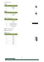
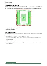
The power board layout shows the connectors and jumpers on the board. Refer to the following picture as a
reference of the pin assignments and the internal connectors.
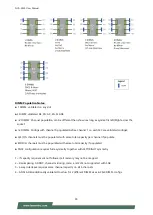
JATX1-4, 24 & 25:
4-pin Power Connector
Pin No.
Description
Pin No.
Description
1
GND
2
GND
3
P3V3
4
P12V
JATXP12V:
4-pin Power Connector
Pin No.
Description
Pin No.
Description
1
GND
2
P12V
3
GND
4
P12V
2
4
3
1
2
1
3
4
Содержание NCA-5530
Страница 1: ...NCA 5530 User Manual Version 1 1 Date of Release 2021 11 17 Network Appliance Platforms...
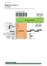
Страница 16: ...NCA 5530 User Manual 16 The block diagram indicates how data flows among components on the motherboard...
Страница 57: ...NCA 5530 User Manual 57...
Страница 59: ...NCA 5530 User Manual 59...
Страница 62: ...NCA 5530 User Manual 62...
Страница 63: ...NCA 5530 User Manual 63 Feature Options Description Smart Fan Mode Configuration None Smart Fan Parameters...
Страница 73: ...NCA 5530 User Manual 73...
Страница 78: ...NCA 5530 User Manual 78...
Страница 80: ...NCA 5530 User Manual 80...
Страница 82: ...NCA 5530 User Manual 82...
Страница 84: ...NCA 5530 User Manual 84 Feature Options Description CPU Socket0 Configuration None None...
Страница 99: ...NCA 5530 User Manual 99...
Страница 117: ...NCA 5530 User Manual 117 APPENDIX E SMART POWER AND RESET BUTTON Smart Power and Reset Button Control by CPLD...


