


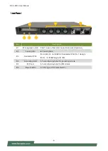


NCA-4035 User Manual
16
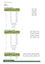
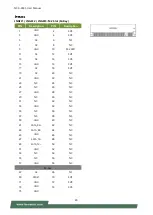
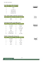
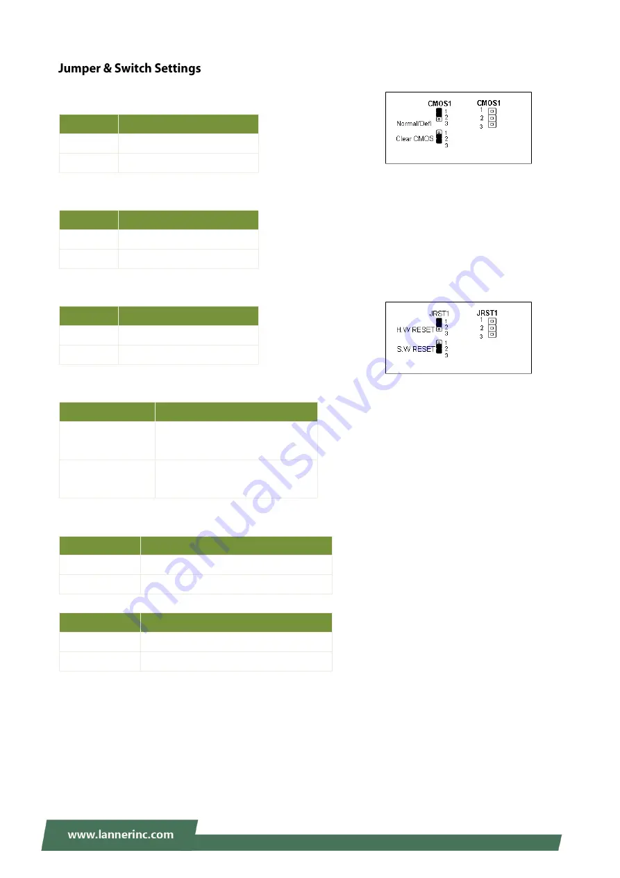
CMOS1: Clear CMOS
CMOS1
Description
1-2
Normal (Default)
2-3
Clear CMOS
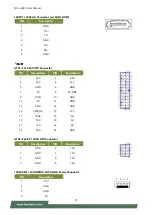
JPWR1: External Power Button (1x2 Pin 2.43mm Wafer)
PIN
Description
1
PS_IN
2
GND
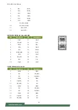
JRST1: Reset Mode Select
PIN
Description
1-2
Hardware Reset
2-3
Software Reset
JDUAL1: Select CS for Flash Fixture
Pin/Switch
Description
1-2 Short,
3-4 Short
Flash 1
st
SPI ROM (Default)
1-3 Short,
2-4 Short
Flash 2
nd
SPI ROM
J13: BIOS Boot Up / Function Select
Pin/Switch
Description
1-3 Short
Boot Up from 1
st
SPI ROM (Default)
3-5 Short
Boot Up from 2
nd
SPI ROM
Pin/Switch
Description
2-4 Short
Enable Dual BIOS (Default)
4-6 Short
Disable Dual BIOS
Содержание NCA-4035
Страница 1: ...1 NCA 4035 User Manual Version 1 0 Date of Release 2022 11 03 Network Appliance Platforms ...
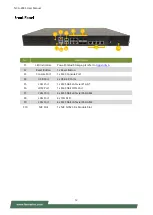
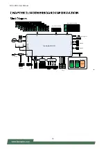
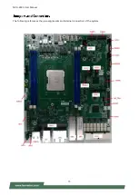
Страница 15: ...NCA 4035 User Manual 15 The following references the pin assignments and internal connectors of the system ...
Страница 60: ...NCA 4035 User Manual 60 ...
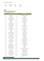
Страница 63: ...NCA 4035 User Manual 63 Feature Options Description Smart Fan Mode Configuration None Smart Fan Parameters ...
Страница 73: ...NCA 4035 User Manual 73 ...
Страница 78: ...NCA 4035 User Manual 78 ...
Страница 80: ...NCA 4035 User Manual 80 ...
Страница 94: ...NCA 4035 User Manual 94 ...
Страница 106: ...NCA 4035 User Manual 106 SMART POWER RESET BUTTON Smart Power and Reset Button Control by CPLD ...


