background image

NCA-1525 User Manual


46 


Feature 

Options 

Description 

Watch Dog Timer 

Enabled 

Disabled


Enables or disables Watch Dog Timer function 

Watch Dog Timer 

Count Mode 

Second Mode 

Minute Mode


Select Second Mode or Minute Mode 

Watch Dog Timer   

Time out Value 

60 

Watch Dog Timer Time out Value. 


Содержание NCA-1525

Страница 1: ...1 NCA 1525 User Manual Version 1 0 Date of Release 2023 02 22 Network Appliance Platforms Hardware Platforms for Network Computing...

Страница 2: ...please visit the Lanner Download Center As certain categories of documents are only available to users who are logged in please be registered for a Lanner Account at http www lannerinc com to access p...

Страница 3: ...Town Changping District Beijing 102208 China T 86 010 82795600 F 86 010 62963250 E service ls china com cn USA Lanner Electronics Inc 47790 Westinghouse Drive Fremont CA 94539 T 1 855 852 6637 F 1 510...

Страница 4: ...void the user s authority to operate this equipment This transmitter must not be co located or operating in conjunction with any other antenna or transmitter Follow these guidelines to ensure general...

Страница 5: ...fectu e par un lectricien form ou une personne form e l lectricit connaissant toutes les sp cifications d installation et d appareil du produit Ne transportez pas l unit en la tenant par le c ble d al...

Страница 6: ...overloading of the circuits might have on overcurrent protection and supply wiring Appropriate consideration of equipment nameplate ratings should be used when addressing this concern Reliable Groundi...

Страница 7: ...e connexion la terre est tr s importante pour prot ger l quipement contre les effets n fastes du bruit externe et r duire les risques d lectrocution en cas de foudre Pour d sinstaller l quipement d br...

Страница 8: ...ear Panel 13 Block Diagram 14 Jumpers and Connectors 15 Opening the Chassis 25 Installing the System Memory 26 Installing M 2 Storage Module Optional 27 Installing Wi Fi Module Card Optional 28 Instal...

Страница 9: ...NCA 1525 User Manual 9 Platform 57 Socket 62 Security 71 Boot Menu 74 Save and Exit Menu 75 Warranty Policy 77...

Страница 10: ...for Wi Fi Module 1x M 2 3042 3052 B Key slot for LTE 5G Module 20G 10G Intel QAT Security Acceleration Your package contains the following items 1x NCA 1525 Network Security Platform 1x Power Adaptor...

Страница 11: ...i PCIe LED Indicators Power Button 1x Power Button with LED Console Port 1x RJ45 Default Bard rate 115200 Console Port USB Port 1x USB 3 0 Port Display Port 1x Display Port without Audio Function Powe...

Страница 12: ...ole Port F5 USB Port 2x USB 3 0 Ports F6 LAN Ports 4x RJ45 GbE via 88E1543 Ethernet Ports with LED F7 LAN Ports 2x 10G SFP Ports with LED F8 LAN Ports 2x 2 5GbE RJ45 Base T via 2xI226 LM Ethernet Port...

Страница 13: ...NCA 1525 User Manual 13 No Description R1 SIM Cover 2x Nano SIM Slots w Cover R2 LED Indicators LED Indicators R3 Antenna 4x SMA Antenna Holes R1 R2 R3...

Страница 14: ...0 88E1543 SGMII LPC SIO 1xPCIE USB2 0 USB3 0 M 2 2242 2280 SATA SSD SPI 1DPC DDR4 2933 2400MHz SO DIMM USB3 1 USB2 0 M 2 3042 3050 3052 2 5G Copper Base T With POE support M 2 3042 3052 M 2 3042 3050...

Страница 15: ...ctors of NCA 1525 JBAT1 RTC Battery Connector Pin Description 1 V_BATTERY 2 GND COM1 Console Port Pin Description 1 COM1_RTS_N 2 COM1_DTR_N 3 COM1_TXD 4 LGND FAN2 FAN1 JOPEN1 J80PORT 1 DYING GASP1 ATX...

Страница 16: ...CONN2 Power PIN Header Pin Description 1 GND 2 PWRON FAN1 System Fan Pin Description 5 SYSFANOUT 4 NC 3 FANIN 2 P12V 1 GND FAN2 CPU Fan Pin Description 5 CPUFANOUT 4 NC 3 CPUFANIN 2 P12V 1 GND J80PORT...

Страница 17: ...RTC2 Clear CMOS 1 2 NORMAL 2 3 CLEAR RTC Pin Description 1 P3V3_RTC 2 SOC_RTEST_N 3 GND JSPIROM1 Flash BIOS Connector Pin Description Pin Description 1 SPI_HD1 2 NC 3 SOC_SPI_CS0_R 4 P3V3_SB_SPI 5 SPI...

Страница 18: ...UIM1_DAT1 35 USB3_HTX_L_DRX_N 36 UIM1_PWR 37 USB3_HTX_L_DRX_P 38 NC 39 GND 40 NC 41 NC 42 NC 43 NC 44 NC 45 GND 46 NC 47 NC 48 NC 49 NC 50 NGFF_LTE_RST 51 GND 52 NC 53 NC 54 NC 55 NC 56 NC 57 GND 58 N...

Страница 19: ...29 NC 30 NC 31 NC 32 NC 33 GND 34 NC 35 NC 36 NC 37 NC 38 NC 39 GND 40 NC 41 SATA_HRX_C_DTX_P 42 NC 43 SATA_HRX_C_DTX_N 44 NC 45 GND 46 NC 47 SATA_HTX_C_DRX_N 48 NC 49 SATA_HTX_C_DRX_P 50 NGFF_STORAGE...

Страница 20: ...LOT_N 12 NC 13 CLK_PCIE_SLOT_P 14 NC 15 GND 16 NC 17 NC 18 GND 19 NC 20 P3V3 21 GND 22 MINI_PCI_RST 23 PEX_RXN 24 P3V3 25 PEX_RXP 26 GND 27 GND 28 NC 29 GND 30 SMB_MPCIE_CLK 31 PEX_TXN_C 32 SMB_MPCIE_...

Страница 21: ...22 UIM1_VPP1 23 NC 24 UIM1_RST1 25 NC 26 UIM1_CLK1 27 GND 28 UIM1_DAT1 29 USB3_HRX_L_DTX_N16 30 UIM1_PWR 31 USB3_HRX_L_DTX_P16 32 NC 33 GND 34 NC 35 USB3_HTX_L_DRX_N16 36 NC 37 USB3_HTX_L_DRX_P16 38...

Страница 22: ...on Pin Description C1 UIM1_PWR C4 UIM1_DAT1 C2 UIM1_RST1 C5 UIM1_VPP1 C3 UIM1_CLK1 C6 GND SW1 Reset Button Pin Description Pin Description 4 GND 3 GND 2 GND 1 SW_RST_GP_N SW2 Power Button Pin Descript...

Страница 23: ...SEL 0 Host 1 Card1 SIM Socket for M2_1 LTE 1st SIM Card J5G_1 5G Module Selection Pin Header 1 2 3 4 5 6 7 8 9 10 short for EM9190 remove for FM980n Pin Description Pin Description 1 PCIE_DIS 2 1 8V 3...

Страница 24: ...FP 0_RS0 3 GND 1 Dying Gasp Board Pin Header1 Pin Description Pin Description 1 P3V3_STBY 2 P3V3 3 P3V3_STBY 4 P3V3 5 P3V3_STBY 6 P3V3 7 GND 8 GND 9 GND 10 GND 11 GND 12 GND 13 P12V_UNDERVOLTAGE 14 RS...

Страница 25: ...ons to shut down the device completely and wear ESD protection gloves when handling the installation steps 1 Power off the system and remove all power connections 2 Locate and remove the six 6 screws...

Страница 26: ...memory module 1 Power off the system and open the chassis cover 2 Locate the system memory slot 3 Align the notch of the module with the socket key in the slot Insert the pins at 30 degrees into the...

Страница 27: ...ower off the system and open the chassis cover 2 Locate the M 2 slot on the motherboard 3 Align the notch of the M 2 memory card with the socket key in the pin slot 4 Insert the M 2 memory card pins a...

Страница 28: ...d 1 Power off the system and open the chassis cover 2 Locate the mPCIe slot on the motherboard 3 Align the notch of the Wi Fi module card with the socket key in the pin slot 4 Insert the Wi Fi module...

Страница 29: ...the two 2 antenna IPEX connectors on the Wi Fi module card 2 Connect the RF cables to the IPEX connectors on the Wi Fi module card and screw the other end of the cables in the antenna holes 3 Then scr...

Страница 30: ...tallation 1 Power off the system and open the chassis cover 2 Locate the M 2 slot on the motherboard 3 Align the notch of the 5G module card with the socket key in the pin slot 4 Insert the 5G module...

Страница 31: ...4 antenna IPEX connectors on the LTE 5G module card 2 Connect the RF cables to the IPEX connectors on the LTE 5G module card and screw the other end of the cables in the antenna holes 3 Then screw on...

Страница 32: ...cover Unscrew the two 2 screw securing the cover 3 Gently remove the SIM slot cover 4 Insert and push the Nano SIM card gold contacts facing downwards all the way in until it clicks into place Repeat...

Страница 33: ...PoE Module Kit includes 1x PoE Module 3x Spacer standoff pillar studs 1x Power Adapter 2 Power off the system and open the chassis cover 3 Locate the PoE Module slot placement 4 Remove the three 3 sc...

Страница 34: ...the chassis rear opening spot and insert the bottom pins into JPOE connector pins 7 Screw in the original three 3 screws to secure the PoE module board 8 Connect the power source pin to the power ada...

Страница 35: ...1 Boot up the system 2 Pressing the Tab or Del key immediately allows you to enter the Setup utility and then you will be directed to the BIOS main screen The instructions for BIOS navigations are as...

Страница 36: ...rnel version CRB code base X64 Compliancy UEFI version PI version Project Version BIOS release version Build Date and Time MM DD YYYY Access Level Administrator User System Date To set the Date use Ta...

Страница 37: ...NCA 1525 User Manual 37 Select the Advanced menu item from the BIOS setup screen to enter the Advanced setup screen Users can select any of the items in the left frame of the screen...

Страница 38: ...show Security Device TCG EFI protocol and INT1A interface will not be available SHA 1 PCR Bank Enabled Disabled Enables or disables SHA 1 PCR Bank SHA256 PCR Bank Enabled Disabled Enables or disables...

Страница 39: ...ode for Win8 Win10 TCG_2 Supports new TCG2 protocol and event format for Win10 or later Physical Presence Spec Version 1 2 1 3 Select to tell OS to support PPI Spec Version 1 2 or 1 3 NOTE Some HCK te...

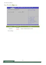
Страница 40: ...NCA 1525 User Manual 40...

Страница 41: ...NCA 1525 User Manual 41 Feature Options Description Serial Port Disabled Enabled Enable or Disable Serial Port COM Device Settings...

Страница 42: ...NCA 1525 User Manual 42 Feature Options Description Serial Port Disabled Enabled Enable or Disable Serial Port COM Device Settings...

Страница 43: ...NCA 1525 User Manual 43 Feature Options Description Smart Fan 2 Mode Manual mode SMART FAN IV Smart Fan 2 Mode Select...

Страница 44: ...NCA 1525 User Manual 44 Feature Options Description Case Open Enabled Disabled Enables or disables Case Open function...

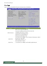
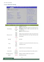
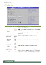
Страница 45: ...NCA 1525 User Manual 45 Feature Options Description Status LED OFF GREEN RED Configures Status LED color...

Страница 46: ...Description Watch Dog Timer Enabled Disabled Enables or disables Watch Dog Timer function Watch Dog Timer Count Mode Second Mode Minute Mode Select Second Mode or Minute Mode Watch Dog Timer Time out...

Страница 47: ...NCA 1525 User Manual 47 Feature Options Description COM0 Console Redirection Enabled Disabled Enables or disables Console Redirection...

Страница 48: ...600 115200 Selects serial port transmission speed The speed must be matched on the other side Long or noisy lines may require lower speeds Data Bits 7 8 Data Bits Parity None Even Odd Mark Space A par...

Страница 49: ...d With this mode enabled only text will be sent This is to capture Terminal data Resolution 100x31 Disabled Enabled Enables or disables extended terminal resolution Putty KeyPad VT100 LINUX XTERM86 SC...

Страница 50: ...NCA 1525 User Manual 50 Feature Options Description SR IOV Support Disabled Enabled If the system has SR IOV capable PCIe Devices this option enables or disables Single Root IO Virtualization Support...

Страница 51: ...Disabled Enables or disables USB Mass Storage Driver Support USB transfer time out 1 sec 5 sec 10 sec 20 sec The time out value for Control Bulk and Interrupt transfers Device reset time out 1 sec 5...

Страница 52: ...Enables Ipv4 HTTP Boot Support If IPV4 is disabled HTTP boot option will not be created Ipv6 PXE Support Disabled Enabled Enables Ipv6 PXE Boot Support If IPV6 is disabled PXE boot option will not be...

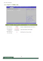
Страница 53: ...NCA 1525 User Manual 53...

Страница 54: ...ure Options Description SDIO Access Mode Auto ADMA SDMA PIO Auto Option Access SD device in DMA mode if controller supports it otherwise in PIO mode DMA Option Access SD device in DMA mode PIO Option...

Страница 55: ...NCA 1525 User Manual 55 Feature Options Description Control PXE Boot from Disabled Lan1 Lan2 Lan3 Lan4 Control PXE Boot from which Lan...

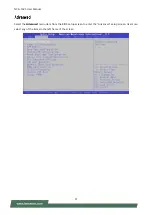
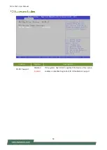
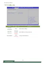
Страница 56: ...NCA 1525 User Manual 56 Feature Options Description TruOpt Optimize Manual Lanner optimization...

Страница 57: ...m Setup screen Users can select any of the items in the left frame of the screen Feature Options Description PCH IO Configuration None PCH Parameters Server ME Configuration None Configure Server ME T...

Страница 58: ...ture Options Description PCH SATA Configuration None Device Options settings Restore AC Power Loss Power On Power Off Last State Select S0 S5 for ACPI state after a G3 Serial IRQ Mode Quiet Continuous...

Страница 59: ...User Manual 59 SATA Configuration Feature Options Description SATA Configuration Disabled Enabled SATA test settings Aggressive LPM Support Disabled Enabled Enable PCH to aggressively enter link powe...

Страница 60: ...NCA 1525 User Manual 60...

Страница 61: ...NCA 1525 User Manual 61 Feature Options Description System Errors Disabled Enabled System Error Enable Disable setup options...

Страница 62: ...ptions Description Processor Configuration None Displays and provides option to change the Processor Settings Memory Configuration None Displays and provides option to change the Memory Settings IIO C...

Страница 63: ...nabled MLC Spatial Prefetcher MSR 1A4h Bit 1 Extended APIC Disabled Enabled Enables disables extended APIC support Note This will enable VT d automatically if x2APIC is enabled Enable Intel R TXT Disa...

Страница 64: ...NCA 1525 User Manual 64 Per Socket Configuration Feature Options Description Core Disable Bitmap Hex 0 0 Enable All cores FFFFFFFFFFF Disable all cores...

Страница 65: ...NCA 1525 User Manual 65 Feature Options Description Memory Topology None Displays memory topology with Dimm population information...

Страница 66: ...nfiguration menu PCI E ASPM Support Global No Per Port L1 Only This option enables disables the ASPM support for all downstream devices PCIe Extended Tag Enable Auto No Yes Auto Enable BIOS sets 8 bit...

Страница 67: ...IOAT Configuration Feature Options Description Sck0 IOAT Config None None Disable TPH No Yes TLP Processing Hint disable Prioritize TPH Disabled Enabled Prioritize TPH Relaxed Ordering No Yes Relaxed...

Страница 68: ...for Directed I O VT d Feature Options Description Intel VT for Directed I O Disabled Enabled Enable Disable Intel Virtualization Technology for Directed I O VT d by reporting the I O device assignment...

Страница 69: ...NCA 1525 User Manual 69 Feature Options Description CPU P State Control None P State Control Configuration Sub Menu include Turbo XE etc...

Страница 70: ...Max Performance Max Efficient Set by Intel Node Manager Select the performance state that the BIOS will set before OS hand off Energy Efficient Turbo Disabled Enabled Energy Efficient Turbo Disable MS...

Страница 71: ...eft frame of the screen Feature Description Administrator Password If ONLY the Administrator s password is set it only limits access to Setup and is only asked for when entering Setup User Password If...

Страница 72: ...e Boot is activated when Platform Key PK is enrolled System mode is User Deployed and CSM function is disabled Secure Boot Mode Standard Custom Customizable Secure Boot mode In Custom mode Secure Boot...

Страница 73: ...t keys on next re boot only when System in Setup Mode Restore Factory keys None Force System to User Mode Configure NVRAM to contain OEM defined factory default Secure Boot keys Enroll Efi Image None...

Страница 74: ...ure Options Description Setup Prompt Timeout 5 The number of seconds to wait for setup activation key 65535 means indefinite waiting Bootup NumLock State On Off Select the keyboard NumLock state Quiet...

Страница 75: ...ave the changes and exit from BIOS Setup in order for the new system configuration parameters to take effect The following window will appear after selecting the Save Changes and Exit option is select...

Страница 76: ...76 Restore Defaults Restore default values for all setup options Select Yes to load Optimized defaults Note The items under Boot Override may not have the same image It would depend on the devices con...

Страница 77: ...omer s expense 5 The following conditions are excluded from this warranty Improper or inadequate maintenance by the customer Unauthorized modification misuse or reversed engineering of the product Ope...

Страница 78: ...NCA 1525 User Manual 78 When requesting RMA service please fill out the following form Without this form enclosed your RMA cannot be processed...

Отзывы: