


NCA-1525 User Manual
34
6.
Align the top power source pin to the
chassis rear opening spot, and insert the
bottom pins into JPOE connector pins.
7.
Screw in the original three (3) screws to
secure the PoE module board.
8.
Connect the power source pin to the
power adapter.
Power Source Pin
JPOE Connector Pins
Front Panel View
Содержание NCA-1525
Страница 40: ...NCA 1525 User Manual 40...
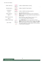
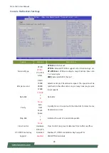
Страница 45: ...NCA 1525 User Manual 45 Feature Options Description Status LED OFF GREEN RED Configures Status LED color...
Страница 53: ...NCA 1525 User Manual 53...
Страница 56: ...NCA 1525 User Manual 56 Feature Options Description TruOpt Optimize Manual Lanner optimization...
Страница 60: ...NCA 1525 User Manual 60...


