IIOT-I530 User Manual
71
Feature
Options
Description
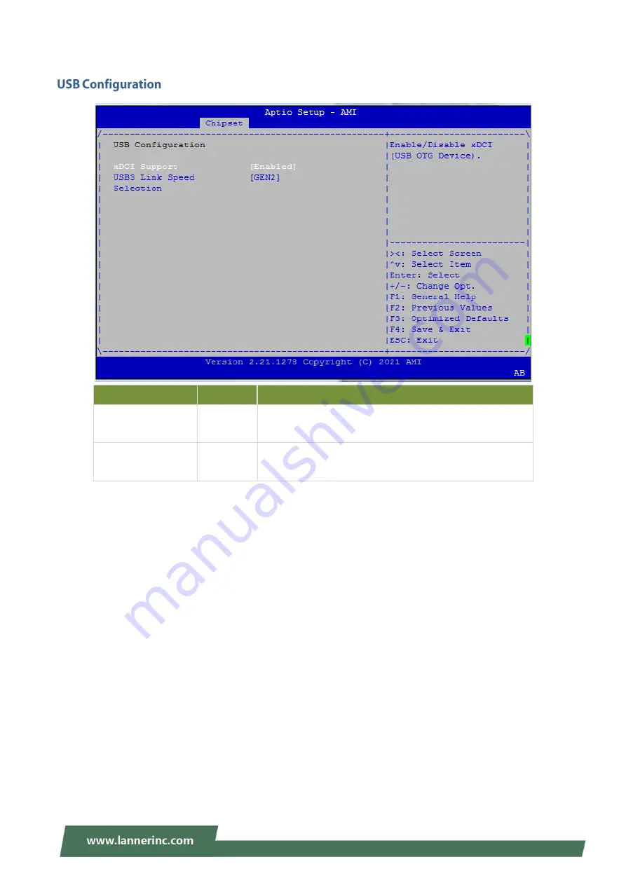
xDCI Support
Enable
Disable
Enable/Disable xDCI (USB OTG Device).
USB3 Link Speed
Selection
GEN1
GEN2
This option is to select USB3 Link Speed GEN1 or GEN2
Страница 1: ...IIOT I530 User Manual Preliminary Draft Release Version 1 2 Date of Release 2022 08 24 Embedded Computing Platform...
Страница 2: ...e is something you should pay special attention to while using the product This mark indicates that there is a caution or warning and it is something that could damage your property or product To obta...
Страница 3: ...Town Changping District Beijing 102208 China T 86 010 82795600 F 86 010 62963250 E service ls china com cn USA Lanner Electronics Inc 47790 Westinghouse Drive Fremont CA 94539 T 1 855 852 6637 F 1 51...
Страница 4: ...ned by turning the equipment off and on the user is encouraged to try to correct the interference by one or more of the following measures Reorient or relocate the receiving antenna Increase the separ...
Страница 5: ...lations regarding safe disposal of lithium BATTERY Disposal of a battery into fire or a hot oven or mechanically crushing or cutting of a battery can result in an explosion Leaving a battery in an ext...
Страница 6: ...amount of airflow required for safe operation of the equipment is not compromised To avoid a hazardous load condition be sure the mechanical loading is even when mounting Consideration should be give...
Страница 7: ...fastes du bruit externe et r duire les risques d lectrocution en cas de foudre Pour d sinstaller l quipement d branchez le c ble de mise la terre apr s avoir teint l appareil Un c ble de mise la terr...
Страница 8: ...n 15 Internal Jumpers and Connector 16 Open the Chassis 24 Protecting the Motherboard 25 Installing the System Memory 26 Installing M 2 Storage Card Optional 28 Installing 5G Module Card Optional 30 I...
Страница 9: ...IIOT I530 User Manual 9 Main Page 43 Advanced Page 44 Chipset 64 Security 73 Boot Menu 76 Save and Exit Menu 77 Warranty Policy 79...
Страница 10: ...ly 2x Ethernet Ports 2x COM Ports 4x USB 3 0 Intel Iris Xe Graphics 2x HDMI 8x DI 4x DO 1x M 2 B Key with Nano SIM for 5G 1x M 2 E Key for Wi Fi 6 1x M 2 M Key for PCIe Gen4 x4 NVME SSD Your package c...
Страница 11: ...Fi 6 Kit 1 0TZW000216000 98619VRSX001 MasterWave Wi Fi 6E FB Antenna 2 080W000908000 Antenna Cable 1 Kit 1 080W000877000 Antenna Cabit 2 Kit 1 020W000489000 RAM SODIM DDR4 TS2GSH64V2E I 16GB with Wide...
Страница 12: ...or SSD HDD mSATA 1x mSATA I O Serial Port 2x RS232 422 485 USB 3 0 4x USB 3 0 Type A LED Power Storage Power on Reset Button 1x Reset Button 1x Power on button Remote Power Switch 1x 2 pin Remote Powe...
Страница 13: ...Power Status LED Indicators F4 Power Switch 1x 2 pin Remote Power Switch F5 SIM Card Slot Dual SIM Card slots F6 Audio Jack 1x Line out and 1x Mic in Jack F7 LAN Port 2x 2 5GB RJ45 Ethernet Ports F8 P...
Страница 14: ...ck R2 Ground Hole 1x Semi shearing hole for grounding R3 COM Port 2x DB9 Male Connectors for RS232 422 485 R4 HDMI Port 2x HDMI Ports R5 Multi IO 1x 20 pin Terminal Block 8 DI 12V 8 DO 12V 100mA Isola...
Страница 15: ...IIOT I530 User Manual 15 The block diagram indicates how data flows among components on the motherboard...
Страница 16: ...he circuit board surrounding the pin header certain feature can be enabled or disable When changing the jumpers make sure your system is completely turned off PW2 24V DC IN Connector PIN No DESCRIPTIO...
Страница 17: ...lt SIN3 3 OFF NXP_RXD 4 OFF NXP_TXD JTAG1 PIN No DESCRIPTION 1 P3V3_STBY 2 NXP_RXD 3 GND 4 NXP_TXD JS2 1 2 COM1 Default PIN No DESCRIPTION 1 COM_RI1 _P 2 COM_RI1 _SEL 3 P5V 4 COM_RI1 _SEL 5 P12V 6 COM...
Страница 18: ...PI_MISO_ROM 6 SOC_SPI_IO3_ROM 7 NC 8 SOC_SPI_CLK_ROM 9 GND 10 SOC_SPI_MOSI_ROM ESPI1 PIN No DESCRIPTION 1 ESPI_CLK 2 ESPI_IO1 3 ESPI_RST 4 ESPI_IO0 5 ESPI_CS0 6 P3V3 7 ESPI_IO3 8 NA 9 ESPI_IO2 10 GND...
Страница 19: ...COM_TXD1_P 4 COM_DTR1 _P 5 GND 6 COM_DSR1 _P 7 COM_RTS1 _P 8 COM_CTS1 _P 9 COM_RI1 _SEL COM2 Serial Port PIN No DESCRIPTION 1 COM_DCD2 _P 2 COM_RXD2_P 3 COM_TXD2_P 4 COM_DTR2 _P 5 GND 6 COM_DSR2 _P 7...
Страница 20: ...TION PIN No DESCRIPTION 1 NC 2 P3V3 3 NC 4 GND 5 NC 6 NC 7 NC 8 NC 9 GND 10 NC 11 NC 12 NC 13 NC 14 NC 15 GND 16 NC 17 NC 18 GND 19 NC 20 NC 21 GND 22 NC 23 SATA1_RXP 24 P3V3 25 SATA1_RXN 26 GND 27 GN...
Страница 21: ...C 63 NC 14 P3V3 39 GND 64 NC 15 GND 40 NC 65 NC 16 P3V3 41 PCIE4_RX_N0 66 NC 17 PCIE4_RX_N2 42 NC 67 NC 18 P3V3 43 PCIE4_RX_P0 68 SUSCLK 19 PCIE4_RX_P2 44 NC 69 P3V3 20 NC 45 GND 70 P3V3 21 GND 46 NC...
Страница 22: ...AN_WAKE_N 48 NC 73 GND 24 V3P3_G1 NC 49 PCH_PCIE_TXP5 74 V3P3_G1 25 M2_1_DPR 50 PERST 1 75 M2_1_Config_2 M2_E_KEY1 M 2 Slots E KEY PIN No DESCRIPTION PIN No DESCRIPTION PIN No DESCRIPTION 1 GND 26 NC...
Страница 23: ...GND 43 PCH_PCIE_RXN9 68 NC 19 GND 44 GPP_F6 69 GND 20 NC 45 GND 70 NC 21 CNV_WR_CLKN 46 CNV_MFUART2_TXD 71 CNVI_WT_CLKN 22 CNV_UART0_RXD 47 CLKOUT_PCIE_P2 72 P3V3 23 CNV_WR_CLKP 48 CNV_MFUART2_RXD 73...
Страница 24: ...er connections to completely shut down the device and wear ESD protection gloves when handling the installation steps 1 Power off the system and disconnect the power cord Turn the system over Unscrew...
Страница 25: ...to efficiently dissipate heat resulting in a better cooling situation The partitions and thermal pads kit contain the following items 2x Metal Partitions 5x Thermal Pads Screw pack All pictures shown...
Страница 26: ...et on the motherboard 2 Next thermal pad placement Remove the protective film from Thermal Pad A included in Partition Thermal Pad Kit and gently place on the motherboard The thermal pad needs to be u...
Страница 27: ...rely inserted a thermal pad needs to be placed over it Remove the protective film from Thermal Pad B included in Partition Thermal Pad Kit and gently place on the module surface 7 Place the metal Part...
Страница 28: ...off the system turn the system over and open the bottom chassis cover Locate the M 2 slot on the motherboard 2 Align the notch of the M 2 memory card with the socket key in the pin slot 3 Insert the...
Страница 29: ...C included in Partition Thermal Pad Kit and gently place on the module surface 6 If a 5G and or Wi Fi module will not be added then place metal Partition B included in Partition Thermal Pad Kit over t...
Страница 30: ...nd open the bottom chassis cover 2 Locate the M 2 B Key slot on the motherboard 2 Align the notch of the 5G module card with the socket key in the pin slot 4 Insert the 5G module card pins at 30 degre...
Страница 31: ...nual 31 6 Next thermal pad placement Remove the protective film from Thermal Pad D included in Partition Thermal Pad Kit and gently place on the module surface Installing 5G Antennas Rear Panel Front...
Страница 32: ...cate the four 4 antenna RF cables pre assembled Locate the four 4 IPEX connectors on the 5G module card 2 Connect A1 A4 A5 A6 RF cables to the 5G module card A1 A4 A6 A5 5G Module Card 5G Module Card...
Страница 33: ...d The SIM socket supports the push push mechanism allowing inserting and ejecting the SIM card to be as easy as one push 1 Locate the door of SIM card slot on the front panel 2 Loosen the twist screw...
Страница 34: ...of the 5G module card with the socket key in the pin slot 4 Insert the Wi Fi module card pins at 30 degrees into the socket until it is fully seated 5 Push down on the module card and secure it with a...
Страница 35: ...Wi Fi Antennas 1 Locate the two 2 antenna RF cables pre assembled Locate the two 2 IPEX connectors on the Wi Fi module card 2 Connect A2 A3 RF cables to the Wi Fi module card Front Panel A2 A3 A3 A2...
Страница 36: ...Then place metal Partition B included in Partition Thermal Pad Kit over the Wi Fi module and secure with one 1 screw on the partition and two 2 screws on the side panel 4 Screw on the two 2 antennas t...
Страница 37: ...the system turn the system around and open the bottom chassis cover 2 Locate the mSATA slot on the motherboard 3 Align the notch of the M 2 memory card with the socket key in the pin slot 4 Insert th...
Страница 38: ...Power off the system turn the system onto its bottom open the bottom chassis cover Locate the 2 5 SATA HDD SSD drive bay on the underside of the bottom chassis cover 2 Place disk drive onto the drive...
Страница 39: ...IIOT I530 User Manual 39 4 Connect the SATA 7 pin signal cable and the SATA 4 pin power cable to their corresponding connectors on the motherboard 5 Plug the standard 7 15 SATA connector to the SSD...
Страница 40: ...e following into considerations when mounting the system onto the wall Note All pictures shown are for illustration purposes only actual product may vary due to specific model or enhancement 1 Fix the...
Страница 41: ...atch the four mounting holes on both brackets 3 Insert four anchoring bolts into the holes 4 Align the four mounting holes on the system s brackets with the four anchoring bolts you just installed on...
Страница 42: ...n select a setup screen for instance Main Advanced Chipset Security Boot and Save Exit select an item option on a setup screen Enter select an item option or enter a sub menu to adjust values for the...
Страница 43: ...ernel version CRB code base X64 Compliancy UEFI version PI version Project Version BIOS release version Build Date and Time MM DD YYYY Access Level Administrator User System Date To set the Date use T...
Страница 44: ...IIOT I530 User Manual 44 Select the Advanced menu item from the BIOS setup screen to enter the Advanced setup screen Users can select any of the items in the left frame of the screen...
Страница 45: ...VMM can utilize the additional hardware capabilities provided by Vanderpool Technology Active Processor Cores All 1 2 3 Number of cores to enable in each processor package Hyper Threading Enabled Dis...
Страница 46: ...IIOT I530 User Manual 46 Feature Options Description ME State Enabled Disabled Configure Management Engine Technology Parameters...
Страница 47: ...IIOT I530 User Manual 47 Feature Options Description Me FW Image Re Flash Enabled Disabled Enable Disable ME FW Image Re Flash function FW Update Enabled Disabled Enable Disable ME FW Update function...
Страница 48: ...ription Automatic OEM Key Revocation Enabled Disabled When enabled BIOS will automatically send HECI command to revoke OEM keys Invoke OEM Key Revocation Enabled Disabled When enabled BIOS will automa...
Страница 49: ...abled Enables or Disables BIOS support for security device O S will not show Security Device TCG EFI protocol and INT1A interface will not be available SHA 1 PCR Bank Enabled Disabled Enables or Disab...
Страница 50: ...torage Hierarchy Endorsement Hierarchy Enabled Disabled Enables or disables Endorsement Hierarchy TPM2 0 UEFI Spec Version TCG_1_2 TCG_2 Select the TCG2 Spec Version TCG_1_2 The Compatible mode for Wi...
Страница 51: ...IIOT I530 User Manual 51...
Страница 52: ...l Port Enabled Disabled Enables or Disables Serial Port COM Device Settings NA IO 3F8h IRQ 4 COM1 MODE Loopback RS232 RS485 Half Duplex RS485 422 Full Duplex Select Com Mode as RS232 RS485 COM1 Termin...
Страница 53: ...l Port Enabled Disabled Enables or Disables Serial Port COM Device Settings NA IO 2F8h IRQ 3 COM1 MODE Loopback RS232 RS485 Half Duplex RS485 422 Full Duplex Select Com Mode as RS232 RS485 COM1 Termin...
Страница 54: ...e reports the CPU temperature System temperature This value reports the System temperature VCORE This value reports the CPU VCORE 3 3V_S This value reports the 3 3V_S Input voltage 5V This value repor...
Страница 55: ...IIOT I530 User Manual 55 Feature Options Description Watch Dog Timer Enabled Disabled Enable or Disable Watch Dog function...
Страница 56: ...0 User Manual 56 Feature Options Description COM0 Console Redirection Enabled Disabled Enables or disables Console Redirection COM1 Console Redirection Enabled Disabled Enables or disables Console Red...
Страница 57: ...Bits per second 9600 19200 38400 57600 115200 Selects serial port transmission speed The speed must be matched on the other side Long or noisy lines may require lower speeds Data Bits 7 8 Data Bits P...
Страница 58: ...for ANSI VT100 terminals Recorder Mode Disabled Enabled With this mode enabled only text will be sent This is to capture Terminal data Resolution 100x31 Disabled Enabled Enables or disables extended...
Страница 59: ...on 80x24 80x25 On Legacy OS the Number of Rows and Columns supported redirection Redirection After POST Always Enable BootLoader When Bootloader is selected then Legacy Console Redirection is disabled...
Страница 60: ...ge should be claimed by XHCI driver USB Mass Storage Driver Support Enabled Disabled Enables or disables USB Mass Storage Driver Support USB transfer time out 1 sec 5 sec 10 sec 20 sec The time out va...
Страница 61: ...support will not be available IPv4 HTTP Support Disabled Enable Enable Disable IPv4 HTTP boot support If disabled IPv4 HTTP boot support will not be available IPv6 PXE Support Disabled Enable Enable D...
Страница 62: ...ty Network Do Not Launch UEFI Legacy Controls the execution of UEFI and Legacy PXE OpROM Storage Do Not Launch UEFI Legacy Controls the execution of UEFI and Legacy Storage OpROM Video Do Not Launch U...
Страница 63: ...IIOT I530 User Manual 63...
Страница 64: ...IIOT I530 User Manual 64 Select the Chipset menu item from the BIOS setup screen to enter the Chipset setup screen Users can select any of the items in the left frame of the screen...
Страница 65: ...d Disabled VT d capability X2APIC Opt Out Enabled Disabled Enable Disable X2APIC_OPT_OUT bit Above 4GB MMIO BIOS assignment Enabled Disabled Enable Disable above 4GB MemoryMappedIO BIOS assignment Thi...
Страница 66: ...TOLUD Dynamic Maximum Value of TOLUD Dynamic assignment would adjust TOLUD automatically based on largest MMIO length of installed graphic controller DDR MEMORY DOWN Config Enabled Disabled DDR MEMOR...
Страница 67: ...IIOT I530 User Manual 67 Feature Options Description Restore AC Power Loss Power On Power Off Specify what state to go to when power is re applied after a power failure G3 state...
Страница 68: ...68 Feature Options Description SATA Controller s Enabled Disabled Enable Disable SATA Device SATA Mode Selection AHCI Intel RST Determines how SATA controller s operate Port 0 Enabled Disabled Enable...
Страница 69: ...t Port 1 Enabled Disabled Enable or Disable SATA Port Hot Plug Enabled Disabled Designates this port as Hot Pluggable External Enabled Disabled Marks this port as external Spin Up Device Enabled Disab...
Страница 70: ...ise all drives spin up at boot SATA Device Type Hard Disk Drive Solid State Drive Identify the SATA port is connected to Solid State Drive or Hard Disk Drive SATA Port 2 DevSlp Enabled Disabled Enable...
Страница 71: ...T I530 User Manual 71 Feature Options Description xDCI Support Enable Disable Enable Disable xDCI USB OTG Device USB3 Link Speed Selection GEN1 GEN2 This option is to select USB3 Link Speed GEN1 or GE...
Страница 72: ...bytes 38h 3Fh in the lower upper 128 byte bank of RTC RAM BIOS Lock Enabled Disabled Enable Disable the PCH BIOS Lock Enable feature Required to be enabled to ensure SMM protection of flash Force unl...
Страница 73: ...left frame of the screen Feature Description Administrator Password If ONLY the Administrator s password is set it only limits access to Setup and is only asked for when entering Setup User Password I...
Страница 74: ...ecure Boot is Enabled Platform Key PK is enrolled and the System is in User mode The mode change requires platform reset Secure Boot Mode Standard Custom Secure Boot mode options Standard or Custom In...
Страница 75: ...orce System to User Mode Install factory default Secure Boot key databases Reset To Setup Mode None Delete all Secure Boot key databases from NVRAM Export Secure Boot variables None Copy NVRAM content...
Страница 76: ...ure Options Description Setup Prompt Timeout 5 The number of seconds to wait for setup activation key 65535 means indefinite waiting Bootup NumLock State On Off Select the keyboard NumLock state Quiet...
Страница 77: ...an select any of the items in the left frame of the screen Discard Changes and Exit Select this option to quit Setup without saving any modifications to the system configuration The following window w...
Страница 78: ...w system configuration parameters to take effect The following window will appear after selecting the Save Changes and Reset option is selected Select Yes to Save Changes and reset Restore Defaults Re...
Страница 79: ...xpense 5 The following conditions are excluded from this warranty Improper or inadequate maintenance by the customer Unauthorized modification misuse or reversed engineering of the product Operation o...
Страница 80: ...IIOT I530 User Manual 80 When requesting RMA service please fill out the following form Without this form enclosed your RMA cannot be processed...