Lanner HTCA-6400 Скачать руководство пользователя страница 9


Electrical Safety Instructions


Before turning on the device, ground the grounding cable of the equipment.  Proper grounding (grounding) is very 
important to protect the equipment against the harmful effects of external noise and to reduce the risk of electrocution 
in the event of a lightning strike.   To uninstall the equipment, disconnect the ground wire after turning off the power.   A 
ground wire is required and the part connecting the conductor must be greater than 4 mm2 or 10 AWG. 

Consignes de sécurité électrique   


Avant d’allumer l’appareil, reliez le câble de mise à la terre de l’équipement à la terre. 


Une bonne mise à la terre (connexion à la terre) est très importante pour protéger l’équipement contre les effets 
néfastes du bruit externe et réduire les risques d’électrocution en cas de foudre. 


Pour désinstaller l’équipement, débranchez le câble de mise à la terre après avoir éteint l’appareil.   


Un câble de mise à la terre est requis et la zone reliant les sections du conducteur doit faire plus de 4 mm2 ou 10 
AWG.   


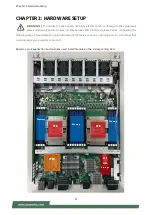
Grounding Procedure for Power Source 


 Loosen the screw of the earthing point. 


 Connect the grounding cable to the ground. 


 The protection device for the power source must provide 30 A current. 


 This protection device must be connected to the power source before power. 


The cable hould 16 AWG 


Procédure de mise à la terre pour source d’alimentation   


Desserrez la vis du terminal de mise à la terre.   


Branchez le câble de mise à la terre à la terre.   


L’appareil de protection pour la source d’alimentation doit fournir 30 A de courant.   


Cet appareil de protection doit être branché à la source d’alimentation avant 
l’alimentation.   


Le câble doit 16 AWG 


Содержание HTCA-6400

Страница 1: ...HTCA 6400 User Manual Version 1 4 Date of Release 2022 03 24 Telecom Datacenter Appliances Hybrid TCA Platforms...

Страница 2: ...ferent font types and icons to make the selected text more transparent and explicable to users Please note that this document contains the following conventions Font Conventions Example Convention Usa...

Страница 3: ...ight and Trademarks This document is copyrighted 2022 by Lanner Electronics Inc All rights are reserved The original manufacturer reserves the right to make improvements to the products described in t...

Страница 4: ...uilongguan Town Changping District Beijing 102208 China T 86 010 82795600 F 86 010 62963250 E service ls china com cn USA Lanner Electronics Inc 47790 Westinghouse Drive Fremont CA 94539 T 1 855 852 6...

Страница 5: ...the user is encouraged to try to correct the interference by one or more of the following measures Reorient or relocate the receiving antenna Increase the separation between the equipment and receive...

Страница 6: ...reux Coupez compl tement l alimentation en teignant l alimentation et en d branchant le cordon d alimentation avant d installer ou de retirer un ch ssis ou de travailler proximit de sources d alimenta...

Страница 7: ...iodically check the resistance value of the antistatic strap which should be between 1 and 10 megohms Mohms S curit de fonctionnement L quipement lectrique g n re de la chaleur La temp rature ambiante...

Страница 8: ...aintained Particular attention should be given to supply connections other than direct connections to the branch circuit e g use of power strips Installation Operation This equipment must be grounded...

Страница 9: ...s du bruit externe et r duire les risques d lectrocution en cas de foudre Pour d sinstaller l quipement d branchez le c ble de mise la terre apr s avoir teint l appareil Un c ble de mise la terre est...

Страница 10: ...board Layout 17 Internal Jumper Connectors 18 Chapter 3 Hardware Setup 21 Accessing the Compute Blade s 22 Installing the CPU s 23 Installing System Memory 28 Installing IPMI Card Optional 30 Installi...

Страница 11: ...Programming Watchdog Timer 92 Appendix B Setting up Console Redirections 93 Appendix C Programming Generation 3 LAN Bypass 94 Appendix D Installing Intel LAN Controller Driver for Linux 95 Appendix E...

Страница 12: ...igned for telecommunication application HTCA 6400 is NEBS compliant Key Features 4 CPU blades in the rear supports 2x 2nd Gen Intel Xeon Scalable Processor Family CPU for each motherboard BCM StrataXG...

Страница 13: ...on 8x 2 5 swappable drive bays Type M 2 M Key Installation 1 x M 2 M Key socket per M B tray I O Reset Button Yes Console 1 x RJ45 USB 1 x Type A IPMI OPMA socket to support IPMI IAC AST2500 Expansion...

Страница 14: ...5 SATA HDD SSD removable trays F3 MGT Port 1x RJ 45 Management port F4 Console Port 1x RJ 45 Console port F5 USB Port 1x USB 2 0 Type A port F6 Switch Blade Max 2x Switch Boards swappable F7 LAN I O B...

Страница 15: ...MGT Port 1x RJ45 Management Port R3 USB Port 1x USB 2 0 R4 VGA Port 1x Video Graphics Array VGA Port R5 Power Button 1x Power Button R6 Cooling Fans 5x Cooling fans per CPU blade R7 Power Supply 4x R...

Страница 16: ...r Manual 16 CHAPTER 2 MOTHERBOARD INFORMATION Block Diagram The block diagram indicates how data flows among components on the motherboard Please refer to the following figure for your motherboard s l...

Страница 17: ...otherboard Information 17 Motherboard Layout The motherboard layout shows the connectors and jumpers on the board Refer to the following picture as a reference of the pin assignments and the internal...

Страница 18: ...Description 1 Detect 2 GND JPWR1 For Power Button detection Pin Description 1 GND 2 Power on JFAN1 JFAN5 For Fan Module Connection Pin Description 1 GND 2 12V 3 RPM sense 4 RPM sense 5 PWM control JV...

Страница 19: ...7 33 39 45 51 57 71 73 75 GND 2 4 12 14 16 18 70 72 74 3 3V 5 PERN3 6 8 20 22 24 26 28 30 32 34 36 38 40 42 44 46 48 56 58 68 NC 7 PERP3 11 PETN3 13 PETP3 17 PERN2 19 PERP2 23 PETN2 25 PETP2 29 PERN1...

Страница 20: ...CON2 For Function Reserved JCMOS1 For Clear CMOS Pin Description 1 2 Normal 2 3 Clear CMOS JHDA_SDO For Flash Descriptor Security Override Pin Description 1 2 Normal 2 3 Override JSPITPM For Lanner TP...

Страница 21: ...ll power sources 2 Please wear ESD protected gloves before conducting the following steps This exclamation point indicates that there is a caution or warning and it is something that could damage your...

Страница 22: ...Please follow the steps below to access the compute blades 1 Select a compute blade you wish to access the internal components 2 Rotate and loosen the captive screws circled in the image below You ma...

Страница 23: ...k to make a PHM Processor Heat Sink Module 2 Install the PHM onto the motherboard Tools Required Tool Description Torque Screwdriver Star T30 Set to 1 36N m or 12 in lbf for tightening the nuts which...

Страница 24: ...Bolster Plate A robust bolster plate is used to assist in PHM alignment for installation while effectively helping eliminate PCB bowing during compression Please locate the Cutout on one of the four...

Страница 25: ...e are two corner cutouts on one heat sink either will do 5 With a little pressure push the four corners of the carrier down to engage their latching features with the corresponding corners of the heat...

Страница 26: ...ent light to ensure there is no contamination or damage prior to the PHM installation 2 Flip the PHM over to align PIN1 of the carrier with the Cutout of the bolster plate 3 Flip the PHM back over so...

Страница 27: ...Use a torque driver to tighten the four nuts to 12 in lbf into the bolster plate following the sequence indicated on the heat sink 1 2 3 4 NOTE When fastening 3 and 4 nuts the gap between the metal s...

Страница 28: ...lots per processor Number of Channels 6 Channels 4 for 1 Dimm per Channel and 2 for 2 Dimm per Channel Supported DIMM Capacity 4GB 8GB 16GB 32GB Memory Size Maximum 512 GB RDIMM 32GB 16 Memory Type DD...

Страница 29: ...emory modules of the same capacity speed and from the same manufacturer are highly recommended However with mixed module speeds the overall speed will be that of the slowest installed memory module Me...

Страница 30: ...ollow the steps for installation 1 Locate the OPMA socket on the motherboard 2 Align the notch of the IPMI card with the socket key in the slot Insert at 30 degrees into the socket until it is fully s...

Страница 31: ...ge card Please follow the steps for installation 1 Locate the M 2 socket on the motherboard 2 Align the notch of the M 2 storage card with the socket key in the slot Insert the storage card at 30 degr...

Страница 32: ...res below demonstrate the hard disk installation method of horizontally mounted disk trays which is exactly the same as that of vertically mounted disk trays except for the orientation 1 Select a driv...

Страница 33: ...epending on ordering configurations the system supports up to 2 switch boards and up to 5 LAN I O blades To replace a new blade board please follow the steps below 1 Rotate and loosen the two captive...

Страница 34: ...oling fans 1 Locate the cooling fans at the rear of CPU blades The fans are covered by a bezel 2 Rotate and loosen the captive screw that locks the bezel for the cooling fans 3 Hold onto the loosened...

Страница 35: ...Units Power supply units may wear out eventually and have to be replaced Please follow the steps below to replace a power supply unit 1 Hold onto the handle of the power supply unit and pull the lock...

Страница 36: ...f the Slide Rail Kit The kit shall include a pack of screws for securing the Rails on the system and a pair of Slide Rails 2 Pull out the Inner Rail and slide it all the way to the end 3 Push the Rele...

Страница 37: ...side panes of the chassis 5 On each side align the screw holes on Inner Rail to the shoulder screws on the chassis and then secure it onto the chassis You can loosen the screws a bit to fix the rail m...

Страница 38: ...8 7 Simply attach both Outer Rails to the front posts of the rack and then secure the rails with the screw assemblies 8 On the rear posts secure each rail with two screw assemblies 9 Pull out the rail...

Страница 39: ...Setup 39 10 Hold the system with its front facing you lift the chassis and gently engage the Inner Rails on the system while aligning them with the Outer Rails as shown in the image 11 Push the chassi...

Страница 40: ...low the steps below 1 Boot up the system 2 Pressing the Tab or Del key immediately allows you to enter the Setup utility and then you will be directed to the BIOS main screen The instructions for BIOS...

Страница 41: ...Kernel version CRB code base X64 Compliancy UEFI version PI version Project Version BIOS release version Build Date and Time MM DD YYYY Access Level Administrator User System Date To set the Date use...

Страница 42: ...HTCA 6400 User Manual 42 Advanced Select the Advanced menu item from the BIOS setup screen to enter the Advanced setup screen Users can select any of the items in the left frame of the screen...

Страница 43: ...Feature Options Description Security Device Support Enabled Disabled Enables or disables BIOS support for security device By disabling this function OS will not show Security Device TCG EFI protocol...

Страница 44: ...disables Security Device NOTE Your computer will reboot during restart in order to change State of the Device Pending operation None TPM Clear Schedules an Operation for the Security Device NOTE Your...

Страница 45: ...Chapter 4 BIOS Setup 45 Trusted Computing TPM 2 0...

Страница 46: ...Platform Hierarchy Storage Hierarchy Enabled Disabled Enables or disables Storage Hierarchy Endorsement Hierarchy Enabled Disabled Enables or disables Endorsement Hierarchy TPM2 0 UEFI Spec Version TC...

Страница 47: ...Chapter 4 BIOS Setup 47 Trusted Computing PTT Enable...

Страница 48: ...atform Hierarchy Storage Hierarchy Enabled Disabled Enables or disables Storage Hierarchy Endorsement Hierarchy Enabled Disabled Enables or disables Endorsement Hierarchy TPM2 0 UEFI Spec Version TCG_...

Страница 49: ...Chapter 4 BIOS Setup 49 AST2500 Super IO Configuration...

Страница 50: ...HTCA 6400 User Manual 50 Serial Port 1 Configuration Feature Options Description Serial Port Enabled Disabled Enables or disables Serial Port 1 Device Settings NA IO 3F8h IRQ 4...

Страница 51: ...Chapter 4 BIOS Setup 51 Serial Port 2 Configuration Feature Options Description Serial Port Enabled Disabled Enables or disables Serial Port 2 Device Settings NA IO 2F8h IRQ 3...

Страница 52: ...HTCA 6400 User Manual 52 Case Open Configuration Feature Options Description Case Open Enabled Disabled Enables or disables Case Open function...

Страница 53: ...Chapter 4 BIOS Setup 53 Control Legacy PXE Boot Feature Options Description SKU Control Legacy PXE Boot From Disabled MGT LAN1 MGT LAN2 Select On Board LAN Boot NCA 6110A...

Страница 54: ...HTCA 6400 User Manual 54 Watch Dog Timer Configuration Feature Options Description Watch Dog Timer Enabled Disabled Enables or disables Watch Dog Timer function...

Страница 55: ...Chapter 4 BIOS Setup 55 Serial Port Console Redirection Feature Options Description COM0 Console Redirection Enabled Disabled Enables or disables Console Redirection...

Страница 56: ...Extended ASCII char set Bits per second 9600 19200 38400 57600 115200 Selects serial port transmission speed The speed must be matched on the other side Long or noisy lines may require lower speeds Da...

Страница 57: ...d terminal resolution Legacy OS Redirection Resolution 80x24 80x25 On Legacy OS the Number of Rows and Columns supported redirection Putty KeyPad VT100 LINUX XTERM86 SCO ESCN VT400 Selects FunctionKey...

Страница 58: ...CA 6400 User Manual 58 Legacy Console Redirection Settings Feature Options Description Legacy Serial Redirection Port COM0 Select a COM port to display redirection of Legacy OS and Legacy OPROM Messag...

Страница 59: ...Disabled Enabled Enables or disables 64bit capable Devices to be Decoded in Above 4G Address Space Only if System Supports 64 bit PCI Decoding SR IOV Support Disabled Enabled If the system has SR IOV...

Страница 60: ...sabled Enabled Enables Ipv4 HTTP Boot Support If IPV4 is disabled HTTP boot option will not be created Ipv6 PXE Support Disabled Enabled Enables Ipv6 PXE Boot Support If IPV6 is disabled PXE boot opti...

Страница 61: ...egacy Controls the execution of UEFI and Legacy PXE OpROM Storage Do Not Launch UEFI Legacy Controls the execution of UEFI and Legacy Storage OpROM Video Do Not Launch UEFI Legacy Controls the executi...

Страница 62: ...ship change should be claimed by XHCI driver USB Mass Storage Driver Support Enabled Disabled Enables or disables USB Mass Storage Driver Support USB transfer time out 1 sec 5 sec 10 sec 20 sec The ti...

Страница 63: ...Chapter 4 BIOS Setup 63 Tru0pt FORM Feature Options Description TruOpt Enabled Manual Lanner Optimization...

Страница 64: ...can select any of the items in the left frame of the screen Feature Options Description PCH Configuration None Displays and provides option to change the PCH Settings Server ME Configuration None Con...

Страница 65: ...CI Express Configuration None PCI Express Configuration settings PCH sSATA Configuration None sSATA devices and settings Restore AC Power Loss Power ON Power Off Last State Select S0 S5 for ACPI state...

Страница 66: ...on PCIe Root Port Function Swapping Disabled Enabled Enable PCIe root port function swapping feature to dynamically assign function 0 to enabled root port Max Read Request Size MRRS 128B MRRS 256B MRR...

Страница 67: ...e Configure as eSATA Disabled Enabled Configures port as External SATA eSATA Spin Up Device Disabled Enabled If enabled for any of ports Staggerred Spin Up will be performed and only the drive switch...

Страница 68: ...HTCA 6400 User Manual 68 Server ME Configuration...

Страница 69: ...Chapter 4 BIOS Setup 69 Runtime Error Logging Feature Options Description System Errors Disabled Enabled System Error Enable Disable setup options...

Страница 70: ...the Processor Settings Memory Configuration None Displays and provides option to change the Memory Settings IIO Configuration None Displays and provides option to change the IIO Settings Advanced Powe...

Страница 71: ...Chapter 4 BIOS Setup 71 Processor Configuration...

Страница 72: ...led Enabled Enables Intel R TXT VMX Disabled Enabled Enables the Vanderpool Technology which takes effect after reboot Enable SMX Disabled Enabled Enables Safer Mode Extensions Hardware Prefetcher Dis...

Страница 73: ...Chapter 4 BIOS Setup 73 Per Socket Configuration Feature Options Description CPU Socket0 Configuration None None CPU Socket1 Configuration None None...

Страница 74: ...HTCA 6400 User Manual 74 CPU Socket0 Configuration Feature Options Description Core Disable Bitmap Hex 0 0 Enable all cores 3fff Disable all cores IOT Cfg Disabled Enabled None...

Страница 75: ...Chapter 4 BIOS Setup 75 CPU Socket1 Configuration Feature Options Description Core Disable Bitmap Hex 0 0 Enable all cores 3fff Disable all cores IOT Cfg Disabled Enabled None...

Страница 76: ...ature Options Description Memory Frequency Auto 800 1000 1066 1200 1333 1400 1600 1800 1866 2000 2133 2200 2400 2600 2666 2800 OvrClk 2933 OvrClk 3000 OvrClk 3200 OvrClk 3400 OvrClk Maximum Memory Fre...

Страница 77: ...Chapter 4 BIOS Setup 77 3600 OvrClk 3733 OvrClk 3800 OvrClk 4000 OvrClk 4200 OvrClk 4266 OvrClk 4400 OvrClk Memory Topology None Displays memory topology with Dimm population information...

Страница 78: ...Intel VT for Directed I O VT d Configuration menu PCI E ASPM Support Global Disabled Per Port L1 Only This option enables disables the ASPM support for all downstream devices PCIe Extended Tag Enable...

Страница 79: ...on Socket 0 PcieBr1D00F0 None Settings related to PCI Express Port 1A Socket 0 PcieBr1D02F0 None Settings related to PCI Express Port 1C Socket 0 PcieBr2D00F0 None Settings related to PCI Express Port...

Страница 80: ...1A Socket 1 PcieBr1D02F0 None Settings related to PCI Express Port 1C Socket 1 PcieBr2D00F0 None Settings related to PCI Express Port 2A Socket 1 PcieBr2D02F0 None Settings related to PCI Express Por...

Страница 81: ...Feature Options Description Sck0 IOAT Config None None Sck1 IOAT Config None None Disable TPH No Yes TLP Processing Hint disable Prioritize TPH Disabled Enabled Prioritize TPH Relaxed Ordering Disabl...

Страница 82: ...6400 User Manual 82 Intel VT for Directed I O VT d Feature Options Description Intel VT for Directed I O VT d Disabled Enabled Press Enter to bring up the Intel VT for Directed I O VT d Configuration...

Страница 83: ...S Setup 83 Advanced Power Management Configuration Feature Options Description CPU P State Control None P State Control Configuration Sub Menu include Turbo XE and etc CPU C State Control None CPU C S...

Страница 84: ...Max Performance Max Efficient Set by Intel Node Manager Select the performance state that the BIOS will set before OS hand off Energy Efficient Turbo Disabled Enabled Energy Efficient Turbo Disable M...

Страница 85: ...escription Autonomous Core C State Disabled Enabled Autonomous Core C State Control CPU C6 report Disabled Enabled Enables or disables CPU C6 ACPI C3 report to OS Enhanced Halt State C1E Disabled Enab...

Страница 86: ...the left frame of the screen Feature Description Administrator Password If ONLY the Administrator s password is set it only limits access to Setup and is only asked for when entering Setup User Passwo...

Страница 87: ...e Boot Disabled Enabled Secure Boot is activated when Platform Key PK is enrolled System mode is User Deployed and CSM function is disabled Secure Boot Mode Standard Custom Secure Boot mode selector I...

Страница 88: ...ows User to provision factory default Secure Boot keys when System is in Setup Mode Install Factory Default keys None Forces System to User Mode install all Factory Default keys Enroll Efi Image None...

Страница 89: ...mpt Timeout 5 The Number of seconds to wait for setup activation key 65535 means indefinite waiting Bootup NumLock State On Off Select the keyboard NumLock state Quiet Boot Disabled Enabled Enables or...

Страница 90: ...system configuration The following window will appear after the Discard Changes and Exit option is selected Select Yes to Discard changes and Exit Setup Save Changes and Reset When Users have complet...

Страница 91: ...tup 91 Restore Defaults Restore default values for all setup options Select Yes to load Optimized defaults Note The items under Boot Override may not be the same it would depend on the devices connect...

Страница 92: ...d to be malfunctioning and the processor s reset signal is asserted Thus the processor will be restarted as if a human operator had cycled the power To execute the utility enter the number of seconds...

Страница 93: ...onsole port of the system and the other end to the serial port of the Remote Client System 2 Configure the following settings in the BIOS Setup menu BIOS Advanced Remote Access Configuration Serial Po...

Страница 94: ...ernal power supply turns on and booting process starts system off or upon software request during run time 4 Software programmable bypass or normal mode 5 Software programmable timer interval JUST ON...

Страница 95: ...x operating system please visit http www lannerinc com support download center drivers enter the product category and download the utility package For the latest driver update please visit Intel downl...

Страница 96: ...ee next section For Parallel Text based LCM Build To build program source code on Linux platform please use the following steps as a guideline 1 Extract the source file tar xzvf plcm_drv_v0XX tgz 0XX...

Страница 97: ...isplay Display Off turning off the LCM display Cursor Off On NOT showing showing the cursor on the LCM display Blinking off On turning off on the cursor blinking Writing Lanner Taiwan displaying the s...

Страница 98: ...o display a character on the LCM screen Clean display select Item 5 to clear up the LCM display Leave select Item 6 to exit the program Test This program is a testing script and runs through the follo...

Страница 99: ...st please reconfirm the setup of xml file in the Guest OS 5 Reboot the Guest OS Note It is necessary for you to install insmod parport ko parport_pc ko and ppdev ko Linux Kernel drivers in virtualizat...

Страница 100: ...stomer s expense 5 The following conditions are excluded from this warranty Improper or inadequate maintenance by the customer Unauthorized modification misuse or reversed engineering of the product O...

Страница 101: ...Appendix F Terms and Conditions 101 RMA Service Request Form When requesting RMA service please fill out the following form Without this form enclosed your RMA cannot be processed...

Отзывы: