Lanier R/C MARINER 40 MK II ARF Скачать руководство пользователя страница 6

6

3.

Using a 1/8” drill, drill half way through the

aileron hole from both top and bottom till the

drill passes through the aileron.

Insert the 6-32 x 2-1/4 allen head bolt into the

top of the aileron.

Thread the bolt all the way till the head is flush

with the top of the aileron.

4.

On the bottom of the aileron, place first the

cup washer then the nylon nut onto the 6-32

bolt.

Using a 3 mm metric allen wrench tighten the

nylon nut all the way down till it rest in the cup

washer and is tight to the aileron.

Thread the nylon adjustable control horn onto

the bolt.

(Note: Thread the side that you can

see the cut threads in the nylon onto the

bolt)

2.

With the aileron servo in place, make a mark

on the aileron at a 90º degree angle to the

trailing edge and in line with the servo. Look

for the control horn hard point under the cov-

ering. This is the location for the control horn.

5.

Thread the 4-40 x 3-1/4” double threaded rod

into the nylon adjustable control horn.

Place a 4-40 hex nut and a metal clevis on the

other end of the threaded rod.

Mount the clevis to the servo arm and place

the clevis clip on the clevis.

6.

Repeat 1 thru 5 for the second aileron.
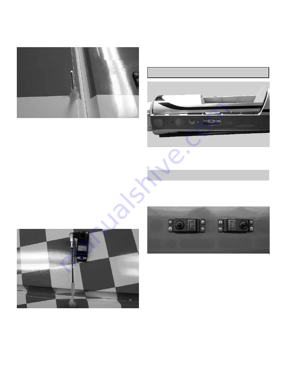
FUSELAGE HATCH

The top front half of the fuselage is a hatch. Remove
the 4-40 socket head bolts on the side of the fuse-
lage to disengage the hatch.

ELEVATOR & RUDDER SERVOS

1.

Collect the following items

(2) Servos

(2) 24” Servo extensions

1.

Locate the servo holes at the rear of the fuse-

lage side.

Remove the covering over both servo holes.

Note: This is the time to decide if you will be using

two servos for the rudder.

2.

Remove the covering over the servo hole on

the other side of the fuselage

Using the 24” servo extensions install all the

servos facing the same direction as shown in

the photo above.

Содержание MARINER 40 MK II ARF

Страница 1: ...area Per the Federal Communications Commission you are required to use only those radio frequencies specified for Model Aircraft LIMITED WARRANTY Lanier RC has inspected and certified the components...

Страница 2: ...ays wing hold down blocks Firewall etc Also during the course of shipping from the manufacturer to our facility in the United States it is not uncommon for the aircraft to experience several changes i...

Страница 3: ...CONSTRUCTION TIPS IMPORTANT ALWAYS READ A FEW STEPS AHEAD This will alert you to coming instructions and will help you plan accordingly COVERING The 87 Yak 54 ARF is covered in a premium polyester fi...

Страница 4: ...liberal amount of 30 minute epoxy Working with 1 hinge at a time place a dab of epoxy and insert the hinge half way into one of the aileron holes Repeat for each of the other hinges for that aileron...

Страница 5: ...the end of the plug to the root rib Mount the inner aileron servo into the wing Aileron 6 Pull the second servo wire out of the wing root rib Plug the two aileron servos into a Y harness Always tape...

Страница 6: ...Look for the control horn hard point under the cov ering This is the location for the control horn 5 Thread the 4 40 x 3 1 4 double threaded rod into the nylon adjustable control horn Place a 4 40 hex...

Страница 7: ...fuselage side Note Always use thread lock on these screws before flying 3 Repeat for the other side of the stabilizer TAIL WHEEL ASSEMBLY 1 Collect the following items 2 Springs 4 1 8 Adjustable Horn...

Страница 8: ...hinge line Drill two 1 16 holes on the marks you just made Use thin CA glue to harden the holes Using the 4 x 3 4 philip head screws mount the tail wheel bracket 3 Install the tail wheel and the whee...

Страница 9: ...ottom of the rudder Insert the 6 32 x 5 1 2 all threaded rod and center it using the 6 washer with a 6 32 lock ing hex nut 3 Place on both ends of the threaded rod a Nylon Adjustable Control Horn Plac...

Страница 10: ...Clevis Clips 2 Nylon Adjustable Control Horn 2 Nylon Adjustable Horn Bracket 2 Nylon Nut 2 Nylon Cup Washer 2 6 32 x 3 Flat Head Screw RUDDER PUSHROD 1 Collect the following items 2 4 40 x 3 1 4 Doub...

Страница 11: ...nto the clevis Repeat steps 2 thru 4 for the other elevator servo Caution Make sure each metal clevis is fully closed and a clip is installed before and after each flight WHEEL AND WHEEL PANTS 1 Colle...

Страница 12: ...ese type of engines any kind of prop strike on the ground or any other type of object can cause structural damage that might not be easily visible When a accident occurs you must check for damage thou...

Страница 13: ...ole allows the carburetor to breath through the firewall into the fuselage Remove for carbu retor breathing 2 The ignition box was mounted below where the fuel tank will be placed FUEL TANK Note The f...

Страница 14: ...Cowl 4 4 40 x 3 4 Button Head Socket Bolt 4 1 4 x 1 4 Silicone tubes You will have to remove any parts of the cowl that rub against the engine Make these openings little at first and slowly make them...

Страница 15: ...4 Nylon Bolt 1 Wing Tube WING BOLTS 2 Slide the wing tube into one of the wing halves Slide the tube thru the fuselage Slide the second wing half onto the wing tube coming out of the fuselage side Pu...

Страница 16: ...the Yak 54 flies Just remember that the further back you go the more sensitive it will become With extreme throws the model can get beyond the abil ity of novice pilots very quickly Good Luck and I h...

Отзывы: