7
Receiving the Griddle
Upon receipt, check for freight damage, both visible and concealed. Visible
damage should be noted on the freight bill at the time of delivery and signed by the
carrier's agent. Concealed loss or damage means loss or damage which does not
become apparent until the merchandise has been unpacked. If concealed loss or
damage is discovered upon unpacking, make a written request for inspection by the
carrier's agent within 15 days of delivery. All packing material should be kept for
inspection. Do not return damaged merchandise to Lang Manufacturing Company.
File your claim with the carrier.
Location
Prior to un-crating, move the griddle as near its intended location as practical. The
crating will help protect the unit from the physical damage normally associated
with moving it through hallways and doorways.
Un-crating
The griddle will arrive completely assembled inside a wood frame covered by
cardboard box and strapped to a skid.
Remove the cardboard cover, cut the
straps and remove the wood frame.
CAUTION:
THE GRIDDLE IS EXTREMELY HEAVY. FOR SAFE
HANDLING, INSTALLER SHOULD OBTAIN HELP AS
NEEDED, OR EMPLOY APPROPRIATE MATERIALS
HANDLING EQUIPMENT (SUCH AS A FORKLIFT,
DOLLY, OR PALLET JACK) TO REMOVE THE UNIT
FROM THE SKID AND MOVE IT TO THE PLACE OF
INSTALLATION.
CAUTION:
ANY STAND, COUNTER OR OTHER DEVICE ON WHICH
GRIDDLE WILL BE LOCATED MUST BE DESIGNED TO
SUPPORT THE WEIGHT OF THE GRIDDLE.
CAUTION:
SHIPPING STRAPS ARE UNDER TENSION AND CAN
SNAP BACK WHEN CUT.
Remove griddle from skid and place in intended location.
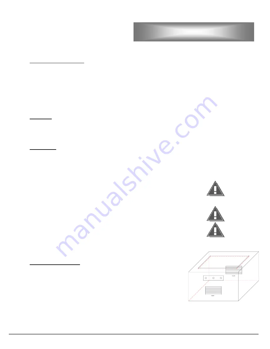
Cabinet Preparation
Cabinet Base must be constructed of non-combustible material.
Cabinet Base must have cross air ventilation. It does not matter if it is on the ends
or sides.
If vents are not installed, the controls may overheat rendering the griddle
inoperative.
For best results provide a knockout for the control panel a minimum of 12-inches
away from the element boxes on the griddle.
UNPACKING
Содержание DI-60
Страница 15: ...15 WIRING DIAGRAM 208 VOLT ...
Страница 16: ...16 WIRING DIAGRAM 240 480 VOLT ...


