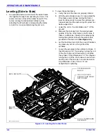
4-22
F-733-1114
OPERATION AND MAINTENANCE
6.
A safety chain is provided with the implement to
insure safe transport.
a.
The safety chain should have a tensile strength
equal to or greater than the gross weight of the
implement. The chain is attached to the lower
hitch clevis hole with two flat washers between
the clamp plates to assure a tight connection.
Always use a 1” diameter Grade 8 bolt for this
connection.
b.
Attach the safety chain to the tractor drawbar
Provide only enough slack in
the chain for turning. Do not use an intermediate
chain support as the attaching point for the chain
on the tractor. Do not pull the implement by the
safety chain.
c.
When unhitching from the tractor attach the hook
end of the chain to a free link close to the hitch
clevis for storage. This will keep the hook off the
ground, reducing corrosion and keep the hook
functioning properly.
d.
Regularly inspect the safety chain for worn,
stretched, or broken links and ends. Replace the
safety chain if it is damaged or deformed in any
way.
7.
Check that tires are of proper size, load rating, and
inflated to manufacture specifications before
transporting. Check wheel lug bolts to insure
tightness.
Figure 4-23: Hitch, Speed Identification Symbol,
and Safety Chain
8.
Know the transport heights and widths of the unit
before transporting. Attachments such as leveling
harrows can increase the transport dimensions of the
implement. Use caution when transporting near
bridges and power lines.
WARNING
9.
Raise the unit to full transport height.
10. Install transport locks on both lift and fold systems.
Do not depend solely on implement hydraulics for
transport.
WARNING
11. Transport during daylight hours whenever possible.
Always use flashing warning lights, except where
such use is prohibited by law. Make sure lights,
reflectors and SMV emblem are clearly visible and
operating. Remove any obstructions such as dirt,
mud, stalks or residue that restricts view before
transporting.
12. To increase stability and reel clearance on center
frame, use hydraulic leveler to roll the unit forward.
Figure 4-24: Installed Transport Locks
6250safetychain
HITCH
WELDMENT
SPEED
IDENTIFICATION SYMBOL
SAFETY
CHAIN
Electrocution can occur without direct contact.
Failure to use transport lock during transport
may result in permanent equipment damage,
serious injury, or death.
6250-transport-extended
3-1/4 X 8 HYDRAULIC
CYLINDER
TRANSPORT
LOCK
3-1/2 X 8 HYDRAULIC
CYLINDER
Содержание 6250
Страница 2: ......
Страница 13: ...STANDARD SPECIFICATIONS 2 5 Table provided for general use NOTES...
Страница 21: ...STANDARD SPECIFICATIONS 2 13 Table provided for general use NOTES...
Страница 28: ...Page Intentionally Blank...
Страница 90: ...NOTES...

