ASSEMBLY INSTRUCTIONS
3-7
Outer Wing Frames
1.
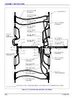
Install double hinge and locks to inner wing with
thrust washer toward rear of the machine using hinge
pin and 1-1/4-7 hex lock nut
Install two fold links per hinge, placing them over
the bushing of the double hinge. Insert 1-8 x 6-1/2
hex head cap screw, wing fold spacer, and 1-8 hex
lock nut to keep fold links stable while installing outer
wing.
2.
Attach outer wing with thrust washer toward front of
machine
3.
Assemble the tire and wheel assemblies to the wing
frames. The wings use 8 bolt wheels and 3” slip-in
spindles. Torque to 85 to 100 ft./lbs.
NOTE
All tire/wheel assemblies are mounted with the valve
stem facing outward.
4.
Install disc gangs to inner wing frames using 3/4-10 x
2 hex head cap screws and hex lock nuts.
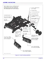
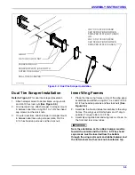
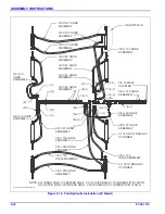
Figure 3-6: Thrust Washer Locations
Figure 3-7: Outer Wing Frame Hinge Assembly
DOUBLE HINGE
1-3/4 THRUST
WASHER
thrust washer locations
6250-45-fold-1
1-1/4-7 HEX LOCK NUT
2-13/16 X 1-13/16
WASHER
ON BOTH SIDES
1-3/4 X 9-3/8 PIN
W/ SNAP RINGS
1-3/4 X 9-3/4 HINGE
PIN
THRUST WASHER
(STAINLESS STEEL)
1-3/4 X 9-3/4 HINGE
PIN
1-3/4 X 9-3/8 PIN
W/ SNAP RINGS
THRUST WASHER
(STAINLESS STEEL)
RIGHT FRONT HINGE SHOWN
Содержание 6250
Страница 2: ......
Страница 13: ...STANDARD SPECIFICATIONS 2 5 Table provided for general use NOTES...
Страница 21: ...STANDARD SPECIFICATIONS 2 13 Table provided for general use NOTES...
Страница 28: ...Page Intentionally Blank...
Страница 90: ...NOTES...

