OPERATION AND MAINTENANCE
4-9
3.
After adjusting the cylinder rod or rods, the radius rod
needs to be adjusted back to a neutral position. This
is accomplished by fully retracting the lift cylinders
and adjusting the radius rod until there is no load on
it, and then tightening the jam nuts on each end.
NOTE
Center frame cylinders may have 1/8” rod exposed when
fully retracted due to the rephasing system.
4.
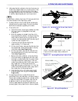
Leveling the Disc side-to-side involves leveling the
wing frame to the center frame. The unit should be
level side-to-side when operating in the field.
5.
To level the unit:
a.
Verify that all tires are properly inflated, and that
the center radius rod adjustment has been
properly set.
b.
With the implement unfolded, raise the unit to
fully extend the lift cylinders. Continue to hold the
tractor lever 30-60 seconds to insure that the
cylinders are fully extended and the rephasing lift
system has been purged of air.
c.
Lower the unit until the disc blades are
approximately 1” off the ground.
d.
On the center frame, measure the distance from
the welded tube in the walking beam to the top
side of the frame
e.
On the wing frame, measure the distance from
the welded washer to the top side of the wing
frame
f.
Measure the same distance on the wing frame.
The wing frames are generally set to the same
distance or slightly higher than the center frame.
The 6250-40 requires subtracting 1” from the
center frame measurement for the wings due to
the smaller tires on the center frame. The
6250-45/50 requires subtracting 1-1/4” from the
center frame measurement for the wings due to
the smaller tires on the center frame.
g.
Adjusting the anchor at the base end of each
wing lift cylinder sets wing frame height
6.
An adjusting wrench is provided to make this
adjustment. It may be necessary to lower the wing to
the ground and relieve weight on the cylinder anchor
to make this adjustment. If required, fully raise the
implement, lower to just above the ground, and
re-verify measurements. Repeat as necessary and
securely tighten the cylinder anchor when complete.
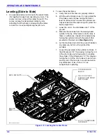
Figure 4-10: Leveling Center Frame from Side to
Side
Figure 4-11: Leveling Wing from Side to Side
Figure 4-12: Wing Lift Adjustment
MEASURE
6250-level-center-frame
6250-wing-lift-measure
MEASURE
NOTE: THIS MEASUREMENT TO BE 1” LESS
THAN CENTER FRAME MEASUREMENT
WING FRAME
3-3/4 x 16 HYDRAULIC
CYLINDER
BASE END
ADJUSTMENT
6250-wing-lift-adjustment
WING LIFT
Содержание 6250
Страница 2: ......
Страница 13: ...STANDARD SPECIFICATIONS 2 5 Table provided for general use NOTES...
Страница 21: ...STANDARD SPECIFICATIONS 2 13 Table provided for general use NOTES...
Страница 28: ...Page Intentionally Blank...
Страница 90: ...NOTES...


