3
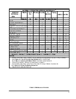
NORMAL OPERATING SERVICE INTERVALS
a
SERVICE
INTERVAL :
ITEM
TIMES
1st 5
Hrs
Weekly Monthly
6
Months
Yearly
LUBE # NOTES
MILES
50
500
2,000 12,000 25,000
LIGHTS
I
I
WIRING & CONNECTIONS
I
I
FASTENERS
I, T
I
b
PIVOT PIN, LIFT PINS AND LOCK
PINS
I
I,L
3
WINCH CABLE ASSEMBLIES
I
I,L
4
g
BRAKE AIR SYSTEM
I
I
I
ABS VALVES
I, C
BRAKE ADJ & WEAR
I
I, T
d
SLACK ADJUSTERS
I
I
L
3
c
CAMSHAFT ASSYS
I
I
L
3
c
HUB OIL
I
I, L
R
5
c
WHEEL BEARINGS
I
I, T
5
c
TIRE INFLATION & WEAR
I
I
e
WHEEL LUG NUTS
I, T
I
I, T
f
HYDRAULIC OIL
I
I
R
1
c
HYDRAULIC FILTER
R
R
HOSES
I
I
I
WINCH GEAR CASE
I
I
2
c
I – Inspect, R – Replace, T– Tighten/ Adjust Torque, L – Lubricate, C – Clean
NOTES:
a. Perform at the time shown. Shorten service intervals when operating in severe or dirty conditions.
b. See
Tables 2-1 and 2-2 (Torque Specifications)
for correct torque.
c. See
Table 4-1 (Lube Specification Chart)
for recommended lubricant.
d. Call Landoll Customer Services for procedures to replace.
e. See Serial Number Plate on the front of the trailer for proper inflation requirements.
f. See
Figure 4-19, Stud Tightening Sequence
.
g. Inspect prior to and after each use.
Table 4-2 Maintenance Schedule
(Inspect & Replace as needed)
,R
Содержание 345B
Страница 3: ...MODEL 345B TRAILER OPERATOR S MANUAL PURCHASED FROM DATE ADDRESS PHONE NO SERIAL NO ...
Страница 8: ......
Страница 12: ......
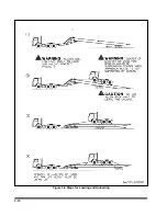
Страница 22: ...3 10 Figure 3 4 Steps for Loading and Unloading ...
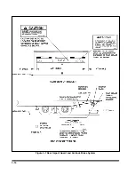
Страница 26: ...3 14 Figure 3 7 Rear Impact Guard and Antilock Brake System ...
Страница 30: ......
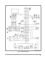
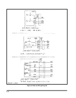
Страница 35: ...4 5 Figure 4 2 345B Wiring Diagram ...
Страница 36: ...4 6 Figure 4 3 Remote Wiring Diagram ...
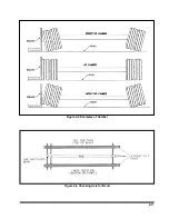
Страница 41: ...4 11 Figure 4 5 Examples of Camber Figure 4 6 Checking Axle for Bend ...
Страница 46: ...4 16 Figure 4 10 Axle and Brake Assembly ...
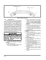
Страница 50: ...4 20 Figure 4 13 Outboard Mount Hub and Drum Figure 4 14 Inboard Mount Hub and Drum ...
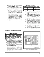
Страница 54: ...4 24 Figure 4 18 Mounting Tires and Wheels Figure 4 19 Stud Tightening Sequence ...
Страница 65: ...5 9 NOTES ...


