background image

3

INSTALLATION

Unpack the Dispenser

1. 

Set shipping carton upright on the floor then cut package 

banding straps and remove.

2.  Open top of carton and remove interior packaging. 
3. 

Lift carton up and off of the unit.

4.  Remove plywood shipping base from unit by moving unit so 

that one side is off the counter top or table allowing access 

to screws on the bottom of the plywood shipping base.

5.  Remove accessory kit and loose parts from ice compartment.

6.  If leg kit has been provided, assemble legs by tilting unit.


If unit is to be transported, it is advisable to leave the 

unit secured to the plywood shipping base.


NOTE


Inspect unit for concealed damage. If evident, notify 


delivering carrier and file a claim against the same.

NOTE

Selecting/Preparing Counter Location

Inspection of Drain Spider

1.  Select a level, well ventilated location that is in close proxim

-

ity to a properly grounded electrical outlet, within five (5) feet 

(1.5 m) of a drain, a water supply that meets the require

-

ments shown in the Specifications section found on page 

4, away from direct sunlight or overhead lighting, and has 

sufficient clearance for air circulation.

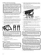
1.  Remove agitator clip and pin from agitator bar.
2.  Remove agitator bar from paddle wheel.
3.  Remove paddle wheel.
4.  Remove ice shroud by lifting back then out of bin.
5.  Locate drain spider and reinstall in the coldplate cavity where 

drain line exits.

6.  Reinstall all components. Ensure agitator clip is locked.


The dispenser should only be installed in a location 

where it can be overseen by trained personnel

NOTE


To assure that beverage service is accessible to all  

customers, Lancer recommends that counter height 

and equipment selection be planned carefully. The 

2010 ADA Standards for Accessible Design states that 

the maximum reach height from the floor should be no 

more than 48” if touch point is less than 10” from the 

front of the counter, or a maximum of 46” if the touch 

point is more than 10” and less than 27” from the front 

of the counter. For more information about the  

customer’s legal requirements for the accessibility of 

installed equipment, refer to 2010 ADA Standards for 

Accessible Design - http://www.ada.gov.

NOTE


The drain spider is located to the right side near the 

front of the bin under the ice shroud. The coldplate has 

a cavity designed to hold the drain spider. During  

shipment, the drain spider may become dislodged from 

its original position. Prior to installing the unit, ensure 

the drain spider is in the correct position. This will 

prevent drain clog issues. Inspect the lower bin area 

and reach under the shroud to ensure the drain spider 

is secure in the coldplate cutout. If the spider is not in 

place, proceed with the following steps.

NOTE


Lancer does 

NOT

 recommend the use of shaved or


flake ice in the dispenser. The ice level should not


exceed the height of the metal bin wall when filled

 manually.

NOTE

4.  Unit may be installed directly on countertop or on legs. If 

installed directly on the counter, unit must be sealed to the 

countertop with an FDA approved sealant. If an icemaker is 

to be mounted on top of dispenser, do not install dispenser 

on legs. 

In order to facilitate proper dispenser drainage, ensure 

that the dispenser is level, front to back and side to 

side. Place a level on the top of the rear edge of the  

dispenser. The bubble must settle between the level 

lines. Repeat this procedure for the remaining three 

sides. Level unit if necessary. For optimum perfor-

mance place the unit at a 0° tilt. The maximum tilt is 5°.

Leveling the Dispenser:


NSF listed units must be sealed to the counter or have 

four (4) inch legs installed.

NOTE


Connecting lines can be run through the back of the 

dispenser or extend down through a counter cutout.

NOTE

5.  Select a location for the remote carbonator, syrup pumps, 

CO

2

 tank, syrup containers, and water filter (recommended).                                                                      

2. 

Sufficient clearance must be provided (if an ice maker is 

not installed) to allow filling ice compartment from a five (5) 

gallon bucket (a minimum of 16 inches is recommended).

3.  Inspect the counter location where the unit is to be installed. 

Verify the selected counter is strong enough to safely sup

-

port the weight of the dispenser, the ice, and the icemaker 

(if necessary) after counter cut out is made. The total weight 

(with icemaker) for this unit could exceed 800 pounds (383.6 

kg).

Содержание Sensation 30

Страница 1: ... your convenience scan this QR code with a mobile device app required for immediate access to other Technical Documents and alternative translations if available pertaining to this unit Contact Lancer Customer Service for assistance as required The dispenser is for indoor use only This unit is not a toy Children should not be supervised not to play with appliance It should not be used by children ...

Страница 2: ...35 lbs 152 kg Empty 275 lbs 125 kg Ice Capacity 250 lbs 113 6 kg Ice Dispensable 185 lbs 84 kg CARBON DIOXIDE CO2 SUPPLY Min Pressure 70 PSIG 0 483 MPA Max Pressure 80 PSIG 0 552 MPA FITTINGS Carbonator Inlet 3 8 inch barb Plain Water Inlet 3 8 inch barb Brand Syrup Inlets 3 8 inch barb ELECTRICAL 115 VAC 60 Hz 3 0 Amps PLAIN WATER SUPPLY Min Flowing Pressure 75 PSIG 0 516 MPA CARBONATED WATER SUP...

Страница 3: ... accessibility of installed equipment refer to 2010 ADA Standards for Accessible Design http www ada gov NOTE The drain spider is located to the right side near the front of the bin under the ice shroud The coldplate has a cavity designed to hold the drain spider During shipment the drain spider may become dislodged from its original position Prior to installing the unit ensure the drain spider is...

Страница 4: ...your IBD s warranty but will result in the inability to control the level of ice in the ice bin which can cause damage to your dispenser ATTENTION 4 Attach Bin Stat Bracket As Shown Recommended Bin Stat Attachment Bulb Tube 5 Ensure the icemaker is installed properly to allow for removal of the Merchandiser 6 Ensure manual fill is accessible 7 Clean and maintain icemaker per manufacturer s instruc...

Страница 5: ...lve cap lever Hold open until water flows from the relief valve then close flip down the relief valve 3 Verify all Bag In Box contains syrup and check all connec tions for leaks 4 Place enough ice in the ice bin to fill approximately 1 2 of the bin before plugging in the unit 5 Connect unit power cord to grounded electical outlet The dispenser must be properly electrically grounded to avoid seriou...

Страница 6: ...cer brix cup activate the valve and capture a sample Verify that the syrup level is even with the water level Use a screwdriver to adjust if needed 9 Remove syrup seperator and reinstall nozzle Replace valve cover 10 Repeat steps 1 8 for each valve 11 Re install merchandiser splash plate and top cover 12 Activate each valve until the carbonator pump comes on Release the button allow carbonator to ...

Страница 7: ... one ounce of cleaner to two gallons of water Prepare a minimum of five gallons of cleaning solution Do not use abrasive cleaners or solvents because they can cause permanent damage to the unit Ensure rinsing is thorough using clean potable water at a temperature of 90 F to 110 F Extended lengths of product lines may require additional cleaning solution 1 Clean cloth towels 2 Bucket 3 Extra nozzle...

Страница 8: ...up system again A B C A Nozzle B Diffuser C Soda Lever Refer to the Automatic Agitation Warning on the first page of this manual NOTE It is recommended to perform this procedure monthly or more often if desired Use the cleaning solution described on page 7 An alternate solution of one part water to one part vinegar may be used to remove water spots and calcium deposits NOTE Always remove the ice c...

Страница 9: ...anitizing Syrup Lines Bag in Box 1 Disconnect syrup lines from BIB s 2 Place syrup lines with BIB connectors in a bucket of warm water 3 Activate each valve to fill the lines with warm water and flush out syrup remaining in the lines 4 Prepare Cleaning Solution described on previous page 5 Place syrup lines with BIB connectors into cleaning solution 6 Activate each valve until lines are filled wit...

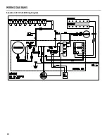
Страница 10: ...10 WIRING DIAGRAMS Sensation 30 115 Volt Wiring Diagram ...

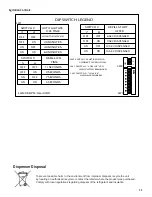
Страница 11: ...SW2 SWITCH 1 MUST BE ON FOR CORRECT OPERATION 2 1 6 SW1 SWITCH 2 LOW ICE ALARM ENABLED 5 8 3 6 8 7 3 8 ON SW2 SW1 6 5 LANCER PN 06 3289 3 SW1 7 1 6 4 2 SW1 SWITCH 1 LOW ICE LED INDICATOR ENABLED 1 4 2 3 1 2 8 1 SWITCH REFILL START AFTER 7 8 OFF OFF 6 SEC DISPENSED OFF ON 9 SEC DISPENSED ON OFF 12 SEC DISPENSED ON ON 15 SEC DISPENSED SWITCH REFILL ON TIME 5 6 OFF OFF 11 SECONDS OFF ON 9 SECONDS ON ...

Страница 12: ...Lancer Corp 800 729 1500 Technical Support Warranty 800 729 1550 custserv lancercorp com lancercorp com ...

Отзывы: