lancer 14400 SERIES Скачать руководство пользователя страница 7

4

N. Clean and sanitize dispenser (see Section 2).
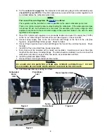
O. Fill unit approximately half full with ice.  Push Chute and check for ice delivery.
P.

Fill unit with ice.

Q. Install Top Cover.

NOTE

Lancer does not recommend the use of shaved, flake, nugget, or pellet ice in dispensers not properly
equipped to do so.

R. Set brix ratio for beverage dispensing valves according to manufacturer's instructions.

1.5

OPTIONAL INSTALLATION OF SOLD-OUT DEVICE

A. An optional Sold-Out Device can be used to automatically shut off the Syrup Pump when the

Package(s) is empty.  This stops the operation of the Pump and the exhaust of gas until a new
syrup package is connected to the Pump. 

B. The Lancer Sold-Out device measures syrup vacuum in the Pump Inlet Line.  When the Syrup

Package is empty, the Pump increases vacuum causing the device to shut off the gas pressure
to stop the Pump.  The Lancer Sold-Out automatically resets, after new Syrup Packages are
connected.

2.

CLEANING AND SANITIZING INSTRUCTIONS

2.1

GENERAL INFORMATION

A. Lancer equipment (new or reconditioned) is shipped from the factory cleaned and sanitized in

accordance with NSF guidelines.  This equipment must be cleaned and sanitized after 
installation is complete, and the operator of the equipment must provide continuous 
maintenance as required by this manual and/or state and local health department guidelines to
ensure proper operation and sanitation requirements are maintained.

NOTE

The cleaning and sanitizing procedures provided herein pertain to the Lancer equipment 
identified by this manual.  If other equipment is being cleaned, follow the guidelines established
for that equipment.

B. Cleaning and sanitizing should be accomplished only by trained personnel.  Sanitary gloves are

to be used during cleaning and sanitizing operations.  Applicable safety precautions must be
observed.  Instruction warnings on the product being used must be followed.

C. Water lines are not to be disconnected during the cleaning and sanitizing of syrup lines to avoid

contamination.

D. Do NOT use strong bleaches or detergents.  They tend to discolor and/or corrode various 

materials.

E. Do NOT use metal scrapers, sharp objects, steel wool, scouring pads, abrasives, solvents, etc.,

on the dispenser.

F.

Do NOT use hot water above 140°F (60°C).  This may damage certain materials.

2.2

REQUIRED CLEANING EQUIPMENT

A. Cleansers (for example, Ivory Liquid, Calgon, etc.) mixed with clean, potable water at a 

temperature of 90 to 110 degrees Fahrenheit should be used to clean equipment.  The mixture
ratio, using Ivory Liquid, is one (1) ounce of cleanser to two (2) gallons of water.  A minimum of
five (5) gallons of cleaning mixture should be prepared.  Any equivalent cleanser may be used
as long as it provides a caustic based, non-perfumed, easily rinsed mixture containing at least
two (2) percent sodium hydroxide (NaOH).  Rinsing must be thorough and use clean, potable
water which is also at a temperature of 90° to 110°F.

NOTE

Extended lengths of product lines may require that an additional volume of cleaning solution be
prepared.

B. Sanitizing solutions should be prepared in accordance with the manufacturer's written 

recommendations and safety guidelines.  The solution must provide 50 to 100 parts per million

Содержание 14400 SERIES

Страница 1: ...ancer all rights reserved 6655 LANCER BLVD SAN ANTONIO TEXAS 78219 USA 210 310 7000 FAX SALES NORTH AMERICA 210 310 7245 INTERNATIONAL SALES 210 310 7242 CUSTOMER SERVICE 210 310 7242 LATIN AMERICA 21...

Страница 2: ...ITATION IT MAY ACTIVATE UNEXPECTEDLY DO NOT PLACE HANDS OR FOREIGN OBJECTS IN THE ICE STORAGE COMPARTMENT WHEN UNIT IS BEING SERVICED CLEANED OR SANITIZED UNPLUG DISPENSER FROM THE POWER SOURCE NOTE L...

Страница 3: ...e __________________________________________ Local Service Phone ________________________________________ ii TABLE OF CONTENTS SPECIFICATIONS i MANUFACTURERS INTRODUCTION ii TABLE OF CONTENTS ii 1 INS...

Страница 4: ...t on the floor B Cut band and remove C Open top of carton and remove interior packing D Lift carton up and off of the dispenser E Remove wood shipping base from the bottom of the dispenser Support dis...

Страница 5: ...cted to a potable water supply must all be sized installed and maintained according to Federal State and Local laws The water supply must be protected by means of an air gap a backflow prevention devi...

Страница 6: ...of the unit See Figure 3 Check for leaks G Connect syrup supply lines to the 3 8 inch barb inlet fittings at the front of the unit See Figure 4 using BIB Bag In Box pumps Check for leaks H Connect fl...

Страница 7: ...er equipment identified by this manual If other equipment is being cleaned follow the guidelines established for that equipment B Cleaning and sanitizing should be accomplished only by trained personn...

Страница 8: ...le body E Fill a cup with clean warm water and rinse nozzle body F Make certain that the nozzle o ring is not torn or otherwise damaged If necessary replace damaged o ring with LANCER PN 02 0231 G Wet...

Страница 9: ...solution Continue rinsing until testing with phenolpthalein shows that the rinse water is free of residual detergent WARNING TO AVOID POSSIBLE PERSONAL INJURY OR PROPERTY DAMAGE DO NOT ATTEMPT TO REMO...

Страница 10: ...nser NOTE Please note that a fresh water rinse cannot follow sanitization of equipment Purge only with the end use product until there is no after taste in the product This is an NSF requirement L Tes...

Страница 11: ...NO PWB C CONFIG BONUS KEY BONUS KEY SETUP V 1 T F M F B F FS 22 NO PWB C CARB WATER SETUP CARB WATER SETUP V1 B1 SODA SOLD OUT 1 OFF FS 22 NO PWB C NUMBER OF VALVES 1 2 Y Y FS 22 NO PWB C GLOBAL CONFI...

Страница 12: ...e remote carbonator pump will activate periodically to fill carbonator with the appropriate amount of water NOTE To check for CO2 leaks close the valve on the CO2 cylinder and observe if the pressure...

Страница 13: ...rom the system After all lines to the Syrup Pump and Syrup Packages are connected and CO2 or air pressure is set the system should be primed as follows A Disconnect Wire to Soda Solenoid or close Shut...

Страница 14: ...id to PC board runs but Ice Door PC Board does not open B Solenoid defective B Replace Solenoid C PC Board defective C Replace PC Board D Solenoid bracket screwed D Unscrew solenoid bracket raise too...

Страница 15: ...IB Pump D Replace pump 4 15 Erratic ratio A Incoming water and or syrup A Check pressure and adjust supply not at minimum flowing pressure B Foreign debris in water and or B Remove flow control from s...

Страница 16: ...ly seated B Reattach door assembly to dispenser 4 22 Circuit breaker tripping A Valve wire harness es A Detect short by disconnecting valve shorted to itself or Faucet harnesses from Switch Panel Plat...

Страница 17: ...w preventer not D Replace backflow preventer allowing water to flow noting the flow direction arrow from pump to coldplate E Probe malfunctioning E Replace Probe F PCB malfunctioning F Replace PCB 5 E...

Страница 18: ...15 6 ILLUSTRATIONS AND PARTS LISTINGS 6 1 FINAL ASSEMBLY 1 2 5 6 3 4 9 10 7 8 11 12 14 15 37 36 13 16 17 18 19 20 21 24 22 23 28 29 30 25 26 27 31 32 33 34 35 38...

Страница 19: ...Shaft Motor IBD 17 23 1373 Agitator Assy FS IBD HEX 18 05 1555 Bearing Agitator Rear IBD 19 10 0762 Pin Hex Design FS 16 20 03 0368 Retainer Pin Agitator IBD R 21 82 3556 Dispensing Wheel Assy Hex 22...

Страница 20: ...03 0368 Retainer Pin Agitator IBD 5 82 3651 Dispensing Wheel Assy Pellet Ice R 6 30 9801 01 Shield Nugget IC R in margin indicates change NOTICE The Pellet Ice components listed on this Instruction S...

Страница 21: ...V1 BLACK BLACK WHITE BLACK WHITE BLACK POWER SUPPLY CONTROLLER BOARD DISPLAY CARB AGI FOT COMM ICE OPTIC ICE DOOR ICE SWITCH KEY SOLD OUT JV1 JV2 JV3 JV4 CARB PROBE POWER CARBONATOR BALLAST ICE AGITAT...

Страница 22: ...1 YEL BLK RED BLK BRN BLK YEL GRY V A L V E M O U N T I N G N O Z Z L E P A N E L I N L E T F I T T I N G S BLU BLK RED GRY S1 3 SODA1 WATER1 S1 4 S1 2 S1 1 IS1 1 IS1 2 IS1 3 VALVE HARNESS DIAGRAM PLU...

Страница 23: ...sia Flat A 24 F Houston Industrial Bldg 32 40 Wang Lung Street Tsuen Wan N T Hong Kong Phone 852 94302585 FAX 852 24082605 e mail patrickco lancer asia com Lancer Authorized Distributors Shanghai Fres...

Страница 24: ...Lancer Europe Web Site www lancereurope be Belgium European Central Office Lancer Europe S A Mechelsesteenweg 592 B 1930 Zaventem Belgium Phone 32 2 755 2390 FAX 32 2 755 2399 e mail info lancereurope...

Отзывы: