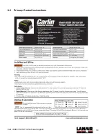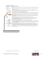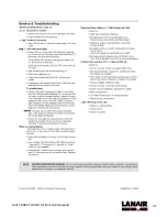
28
Call 1-888-370-6531 for Technical Support
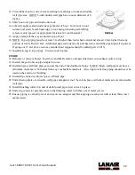
1. With the burner power shut off, remove the air filter by sliding it off.
2. Remove the air tubing from the quick connect fitting, by pushing in the metal ring
while pulling the tubing out.
3. Remove the two hex bolts with a 7/16” wrench and slide the air compressor
assembly out of the burner body.
4. Use a 9/64” Allen wrench to carefully remove the air compressor cover plate and
carbon gasket.
5. Inspect the carbon gasket for wear—reverse if worn or replace as necessary.
6. Spin the compressor shaft by hand and observe the vanes.
7. If the vanes do not move in their slots as the rotor turns, clean the vanes. Clean the
vanes and compressor body using Gast compressor cleaning fluid or suitable
equivalent.
Note: Do not use oils or petroleum solvents, such as engine degreasers. These fluids
leave unwanted residues behind that may cause the vanes to stick and/or bind. If the
vanes are worn out, you may purchase a vane replacement kit (PN 75000166).
8. Reassemble the air compressor. Be careful not to over-tighten the cover plate.
9. While the air compressor is out of the burner, remove the interior coupling that
transmits rotation from the motor gear grip to the air compressor gear grip.
10. Inspect the coupling hubs and elastic sleeve for wear or damage. Replace if needed.
(the motor may also need to be detached from the burner to for inspection/service)
11. Reinstall the coupling, compressor assembly, air tube, and air filter. Ensure the
coupling sleeve ends align properly with the coupling hubs. If any part of the coupling
needs to be replaced go to step 12. Otherwise go to step 13.
12. On the motor side, the blower wheel should be set so that 7/8” of the shaft is exposed
when the coupling hub is removed. Fully seat the coupling hub with the larger interior
dimension against the blower hub and ensure that the set screw is tightened securely
to the flat portion of the shaft. Slide the coupling’s elastic sleeve onto the motor-side
hub, then secure the motor to the burner housing. Secure the coupling hub with the
smaller interior dimension as far onto the compressor shaft as possible such that the
set screw is still on the flat portion of the shaft. Secure the set screw to the flat of the
compressor shaft. Slowly slide the compressor and coupling hub into the coupling
sleeve and secure the air compressor to the burner housing. Make sure the tabs on
the spacer plate under the air compressor align with the bolt holes before tightening
and verify the compressor is fully seated once complete.
13. Run the burner and confirm/adjust the air pressure to 3 - 4 psi.
Coupling from Motor to Compressor
Elastic Sleeve
Compressor-side Hub
Air Compressor
Burner Motor
Motor-side Hub
Blower Wheel
Содержание MX 75
Страница 2: ......
Страница 41: ...8 Appendices 8 1 Wiring Diagram ...
Страница 42: ......
Страница 43: ...34 Call 1 888 370 6531 for Technical Support 8 2 Primary Control Instructions ...
Страница 44: ...35 Call 1 888 370 6531 for Technical Support Not used with RES 75 kBTU h units ...
Страница 45: ...36 Call 1 888 370 6531 for Technical Support No latch up with RES 75 kBTU h units ...
Страница 46: ...37 Call 1 888 370 6531 for Technical Support ...
Страница 54: ...45 Call 1 888 370 6531 for Technical Support 9 ...


