25
Call 1-888-370-6531 for Technical Support
Settings for Retention Head & Electrodes
Inspect the locations of all the components. Use the following specifications:
The Electrode Gap: 3/32” (2.4 mm). If adjustments are necessary, use needle-nose
pliers to carefully bend electrode wires. Replace the electrode if the wires are worn
significantly or if the ceramic is cracked.
Electrode Tips should be 1/16” (1.6 mm) behind the end of the Nozzle.
Nozzle protrudes approximately 1/8” (3 mm) beyond Retention Head vanes.
Vertical location of electrode wires: 7/16” (1.6 mm) from center of nozzle to tips of wires.
Flame Retention Head recessed inside Air Tube
1/16 (1.5 mm).
Nozzle should extend approx. 1/8”
(3 mm) beyond Air Vanes.
Retention Head
Air Plate
Center
Head
within Air
Tube.
7/16” (11 mm)
1/16” (1.6 mm)
(Electrode behind tip)
Air Vanes
Air Tube
3/32” (2.4 mm) Gap
Align Tab on Flame Retention
Head with Slot in Electrode.
Nozzle
Assembly
Spinner
O-Ring
Содержание MX 75
Страница 2: ......
Страница 41: ...8 Appendices 8 1 Wiring Diagram ...
Страница 42: ......
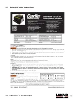
Страница 43: ...34 Call 1 888 370 6531 for Technical Support 8 2 Primary Control Instructions ...
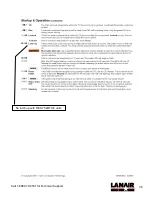
Страница 44: ...35 Call 1 888 370 6531 for Technical Support Not used with RES 75 kBTU h units ...
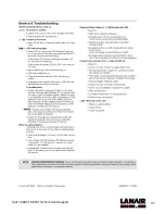
Страница 45: ...36 Call 1 888 370 6531 for Technical Support No latch up with RES 75 kBTU h units ...
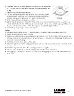
Страница 46: ...37 Call 1 888 370 6531 for Technical Support ...
Страница 54: ...45 Call 1 888 370 6531 for Technical Support 9 ...


