background image

TAURA D MCA

25

EN

cod. 3541A212  -  04/2012  (Rev. 00)

4.3 Maintenance
Periodical check

To ensure correct operation of the unit over time, have qualified personnel carry out a
yearly check, providing for the following:

The control and safety devices (gas valve, flow meter, thermostats, etc.) must func-
tion correctly.

The fume exhaust circuit must be perfectly efficient.
(Sealed chamber boiler: fan, pressure switch, etc. -The sealed chamber must be
tight: seals, cable glands, etc.)
(Open chamber boiler: anti-backflow device, fume thermostat, etc.)

The air-fume end piece and ducts must be free of obstructions and leaks

The burner and exchanger must be clean and free of deposits. For possible cleaning
do not use chemical products or wire brushes.

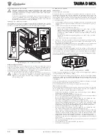
The electrode must be properly positioned and free of scale.

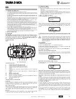
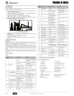
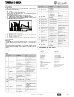
fig. 12 - Electrode positioning

The gas and water systems must be airtight.

The water pressure in the cold water system must be about 1 bar; otherwise, bring
it to that value.

The circulating pump must not be blocked.

The expansion tank must be filled.

The gas flow and pressure must correspond to that given in the respective tables.

4.4 Troubleshooting
Diagnostics

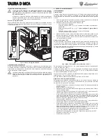
The boiler is equipped with an advanced self-diagnosis system. In case of a boiler fault,
the display will flash together with the fault symbol (detail 11 - fig. 1) indicating the fault
code.
There are faults that cause permanent shutdown (marked with the letter "

A

"): to restore

operation, press the RESET button (detail 6 - fig. 1) for 1 second or RESET on the op-
tional remote timer control if installed; if the boiler fails to start, it is necessary to eliminate
the fault.
Faults marked with the letter "

F

" cause temporary shutdowns that are automatically reset

as soon as the value returns within the boiler's normal working range.

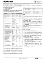
List of faults

Table. 2

5. TECHNICAL DATA AND CHARACTERISTICS

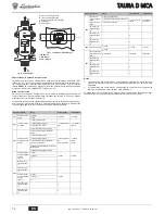
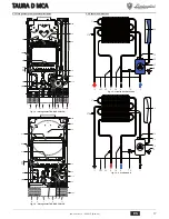
Table. 3 - Legenda figure cap. 5

Fault
code

Fault

Possible cause

Cure

A01

No burner ignition

No gas

Check the regular gas flow to the 
boiler and that the air has been elimi-
nated from the pipes

Ignition/detection electrode fault

Check the wiring of the electrode and 
that it is correctly positioned and free 
of any deposits

Faulty gas valve

Check the gas valve and replace it if 
necessary

Gas valve wiring disconnected

Check the wiring

Ignition power too low

Adjust the ignition power

A02

Flame present signal with 
burner off

Electrode fault

Check the ionisation electrode wiring

Card fault

Check the card

A03

Overtemperature protec-
tion activation

Heating sensor damaged

Check the correct positioning and 
operation of the heating sensor

No water circulation in the system Check the circulating pump
Air in the system

Vent the system

F04

Fume thermostat interven-
tion (after intervention of the 
fume thermostat, boiler 
operation is prevented for 
20 minutes)

Fume thermostat contact open

Check the thermostat

Wiring disconnected

Check the wiring

Flue obstructed or not correctly 
sized

Check the flue

F05

Card parameter fault

Wrong card parameter setting

Check the card parameter and modify 
it if necessary

A06

No flame after the ignition 
phase

Low pressure in the gas system

Check the gas pressure

Burner minimum pressure setting Check the pressures

F07

Card parameter fault

Wrong card parameter setting

Check the card parameter and modify 
it if necessary

A09

Gas valve fault

Wiring disconnected

Check the wiring

Faulty gas valve

Check the gas valve and replace it if 
necessary

F10

Delivery sensor 1 fault

Sensor damaged

Check the wiring or replace the sen-
sor

Wiring shorted
Wiring disconnected

±

 0,5

=

=

F11

DHW sensor fault

Sensor damaged

Check the wiring or replace the sen-
sor

Wiring shorted
Wiring disconnected

F14

Delivery sensor 2 fault

Sensor damaged

Check the wiring or replace the sen-
sor

Wiring shorted
Wiring disconnected

A16

Gas valve fault

Wiring disconnected

Check the wiring

Faulty gas valve

Check the gas valve and replace it if 
necessary

F20

Card parameter fault

Wrong card parameter setting

Check the card parameter and modify 
it if necessary

A21

Card parameter fault

Wrong card parameter setting

Check the card parameter and modify 
it if necessary

A23

Card parameter fault

Wrong card parameter setting

Check the card parameter and modify 
it if necessary

A24

Card parameter fault

Wrong card parameter setting

Check the card parameter and modify 
it if necessary

F34

Supply voltage under 180V. Electric mains trouble

Check the electrical system

F35

Faulty mains frequency

Electric mains trouble

Check the electrical system

F37

Incorrect system water 
pressure

Pressure too low

Fill the system

Water pressure switch damaged 
or not connected

Check the sensor

F39

External probe fault

Probe damaged or wiring shorted

Check the wiring or replace the sen-
sor

Probe disconnected after activat-
ing the sliding temperature

Reconnect the external probe or disa-
ble the sliding temperature

A41

Sensor positioning

Delivery sensor or DHW sensor 
detached from the pipe

Check the correct positioning and 
operation of the sensors

F42

Heating sensor fault

Sensor damaged

Replace the sensor

F43

Exchanger protection acti-
vation.

No system H

2

O circulation

Check the circulating pump

Air in the system

Vent the system

F50

Gas valve fault

Modulating Operator wiring dis-
connected

Check the wiring

Faulty gas valve

Check the gas valve and replace it if 
necessary

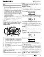
7

Gas inlet

44

Gas valve

8

Domestic hot water outlet

56

Expansion tank

9

Cold water inlet

72

Room thermostat (optional)

10

System delivery

74

System filling cock

11

System return

78

Anti-backflow device

14

Safety valve

81

Ignition and detection electrode

20

Burner assembly

114

Water pressure switch

21

Main nozzle

126

Fume thermostat

22

Burner

138

External probe

27

Copper exchanger for heating and hot 
water

139

Room unit

32

Heating circulating pump

278

Double sensor ( Heating)

36

Automatic air vent

290

Antiwind grille (optional)

38

Flowswitch

340

Bypass pipe

42

DHW temperature sensor

Fault
code

Fault

Possible cause

Cure

Содержание TAURA D 24 MCA

Страница 1: ...F 143 677 322 161 60 60 86 95 30 24 5 24 5 24 5 30 121 95 89 60 60 36 204 158 60 198 5 201 5 208 A B C D E F IT ISTRUZIONE PER L USO L INSTALLAZIONE E LA MANUTENZIONE ES INSTRUCCIONES DE USO INSTALACI...

Страница 2: ...ndata riscaldamento part 11 fig 1 e durante il tempo di attesa riscaldamento la scritta d2 Sanitario Durante la richiesta sanitario generata dal prelievo d acqua calda sanitaria il display visualizza...

Страница 3: ...dima metallica per tracciare sul muro i punti di foratura Il fissaggio alla parete deve garantire un sostegno stabile ed efficace del generatore A Se l apparecchio viene racchiuso entro mobili o monta...

Страница 4: ...tabella dati tecnici per il tipo di gas utilizzato 4 Applicare la targhetta adesiva contenuta nel kit di trasformazione vicino alla targhet ta dei dati tecnici per comprovare l avvenuta trasformazion...

Страница 5: ...trica Valvola gas R Uscita gas S Entrata gas fig 11 Connessione valvola gas TYPE SGV100 Pi max 65 mbar 24 Vdc class B A Indice Descrizione Range Default TAURA D MCA b01 Selezione tipo gas 0 Metano 0 M...

Страница 6: ...o richiesto Verificare che non vi siano liquidi o materiali infiammabili nelle immediate vicinanze della caldaia Verifiche durante il funzionamento Accendere l apparecchio Assicurarsi della tenuta del...

Страница 7: ...n sionato oppure ostruito Verificare la canna fumaria F05 Anomalia parametri scheda Errata impostazione parametro scheda Verificare ed eventualmente modifi care il parametro scheda A06 Mancanza fiamma...

Страница 8: ...enerale TAURA D 32 MCA 5 2 Schemi idraulici fig 15 Circuito Riscaldamento fig 16 Circuito Sanitario 10 8 7 38 9 11 32 44 74 36 114 14 56 78 42 20 21 22 126 81 290 27 278 340 10 8 7 38 9 11 32 44 74 36...

Страница 9: ...ruciatore G20 mbar 1 5 1 5 Portata gas max G20 m3 h 2 73 3 64 Portata gas min G20 m3 h 0 88 1 22 Ugelli bruciatore G31 n x 11 x 0 79 15 x 0 79 Pressione gas alimentazione G31 mbar 37 37 Pressione gas...

Страница 10: ...TAURA D MCA 10 IT cod 3541A212 04 2012 Rev 00 5 5 Schema elettrico fig 21 Circuito elettrico 81 1kW L N 230V 50 Hz 32 L N T T 278 T 42 4 3 2 1 44 38 114 ABM01 126 72 139 138...

Страница 11: ...agua sanitaria generada por una extracci n en la pantalla 11 fig 1 aparece la temperatura actual de salida del ACS alternada con la indicaci n SA sanitaria adem s de la indicaci n d1 durante el tiempo...

Страница 12: ...red debe ser firme y estable A Si el aparato se instala dentro de un mueble o se adosa a otros elementos ha de quedar un espacio libre para desmontar la carcasa y realizar las actividades normales de...

Страница 13: ...TEST Pulsar simult neamente las teclas de regulaci n de la temperatura de la calefacci n 3 y 4 fig 1 durante 5 segundos para activar el modo TEST La caldera se enciende con la potencia de calefacci n...

Страница 14: ...lvula del gas R Salida de gas S Entrada de gas fig 11 Conexi n de la v lvula de gas TYPE SGV100 Pi m x 65 mbar 24 Vcc clase B A ndice Descripci n Rango Predeterminado TAURA D MCA b01 Selecci n del tip...

Страница 15: ...ue la presi n del gas de calefacci n tenga el valor indicado Controlar que no haya l quidos o materiales inflamables cerca de la caldera Controles durante el funcionamiento Encender el aparato Comprob...

Страница 16: ...ficarlo si corresponde A06 No hay llama tras la fase de encendido Baja presi n en la instalaci n de gas Controlar la presi n del gas Regulaci n de la presi n m nima del quemador Controlar las presione...

Страница 17: ...eneral TAURA D 32 MCA 5 2 Esquemas hidr ulicos fig 15 Circuito de calefacci n fig 16 Circuito de AS 10 8 7 38 9 11 32 44 74 36 114 14 56 78 42 20 21 22 126 81 290 27 278 340 10 8 7 38 9 11 32 44 74 36...

Страница 18: ...quemador con G20 mbar 12 12 Presi n m nima quemador con G20 mbar 1 5 1 5 Caudal m ximo G20 m3 h 2 73 3 64 Caudal m nimo G20 m3 h 0 88 1 22 Inyectores quemador G31 n x 11 x 0 79 15 x 0 79 Presi n de al...

Страница 19: ...TAURA D MCA 19 ES cod 3541A212 04 2012 Rev 00 5 5 Esquema el ctrico fig 21 Circuito el ctrico 81 1kW L N 230V 50 Hz 32 L N T T 278 T 42 4 3 2 1 44 38 114 ABM01 126 72 139 138...

Страница 20: ...er the display shows the actual DHW outlet temperature detail 11 fig 1 alternating with the message SA DHW and during DHW standby time the message d1 Fault In case of a fault see cap 4 4 the display s...

Страница 21: ...nd hook the boiler on it A metal template for marking the drilling points on the wall is avail able on request The wall fixing must ensure stable and effective support for the gener ator A If the unit...

Страница 22: ...para graph setting the values given in the technical data table for the type of gas used 4 Apply the sticker contained in the conversion kit near the dataplate as proof of the conversion TEST mode act...

Страница 23: ...ntents Description Range Default TAURA D MCA b01 Gas type selection 0 Natural gas 0 Natural Gas 0 Natural Gas 1 LPG b02 Boiler type selec tion 1 Bithermal instantaneous 1 Bithermal instantaneous 1 Bit...

Страница 24: ...aterials in the immediate vicinity of the boiler Checks during operation Switch the unit on Check the tightness of the fuel circuit and water systems Check the efficiency of the flue and air fume duct...

Страница 25: ...ing Flue obstructed or not correctly sized Check the flue F05 Card parameter fault Wrong card parameter setting Check the card parameter and modify it if necessary A06 No flame after the ignition phas...

Страница 26: ...eral view TAURA D 32 MCA 5 2 Plumbing diagrams fig 15 Heating Circuit fig 16 DHW Circuit 10 8 7 38 9 11 32 44 74 36 114 14 56 78 42 20 21 22 126 81 290 27 278 340 10 8 7 38 9 11 32 44 74 36 114 14 56...

Страница 27: ...in gas pressure at burner G20 mbar 1 5 1 5 Max gas delivery G20 m3 h 2 73 3 64 Min gas delivery G20 m3 h 0 88 1 22 Burner nozzles G31 no x 11 x 0 79 15 x 0 79 Gas supply pressure G31 mbar 37 37 Max ga...

Страница 28: ...TAURA D MCA 28 EN cod 3541A212 04 2012 Rev 00 5 5 Wiring diagram fig 21 Electrical circuit 81 1kW L N 230V 50 Hz 32 L N T T 278 T 42 4 3 2 1 44 38 114 ABM01 126 72 139 138...

Страница 29: ...fig 1 visualise la temp rature actuelle du d part du chauffage part 11 et pendant le temps d attente chauffage l indication d2 Sanitaire Pendant la demande sanitaire par pr l vement d eau sanitaire l...

Страница 30: ...pr voir de l espace pour le d montage de l habillage et pour l entretien normal 3 3 Raccordements hydrauliques Avertissements B L vacuation de la soupape de s ret doit tre raccord e un entonnoir d cou...

Страница 31: ...ns le tableau des donn es techni ques pour le type de gaz utilis 4 Appliquer la plaquette adh sive contenue dans le kit de transformation pr s de la plaquette des donn es techniques en vue de signaler...

Страница 32: ...ape de gaz R Sortie gaz S Arriv e gaz fig 11 Connexion soupape de gaz TYPE SGV100 Pi maxi 65 mbar 24 Vdc class B A Som maire Description Plage D faut TAURA D MCA b01 S lection type de gaz 0 M thane 0...

Страница 33: ...y ait pas de liquides ou de mat riaux inflammables dans les alentours imm diats de la chaudi re V rifications en cours de fonctionnement Mettre l appareil en marche S assurer de l tanch it des circuit...

Страница 34: ...rompu V rifier le c blage Conduit de chemin e non cor rectement dimensionn ou obstru V rifier le conduit de fum e F05 Anomalie param tres carte Mauvais param trage de la carte V rifier et ventuellemen...

Страница 35: ...n rale TAURA D 32 MCA 5 2 Sch mas hydrauliques fig 15 Circuit Chauffage fig 16 Circuit Sanitaire 10 8 7 38 9 11 32 44 74 36 114 14 56 78 42 20 21 22 126 81 290 27 278 340 10 8 7 38 9 11 32 44 74 36 11...

Страница 36: ...ur G20 mbar 1 5 1 5 D bit gaz puissance maxi G20 m h 2 73 3 64 D bit gaz puissance mini G20 m h 0 88 1 22 Gicleurs br leur G31 nbre x 11 x 0 79 15 x 0 79 Pression d alimentation gaz G31 mbar 37 37 Pre...

Страница 37: ...TAURA D MCA 37 FR cod 3541A212 04 2012 Rev 00 5 5 Sch ma lectrique fig 21 Circuit lectrique 81 1kW L N 230V 50 Hz 32 L N T T 278 T 42 4 3 2 1 44 38 114 ABM01 126 72 139 138...

Страница 38: ...O PH WKQ QGHL K SA QHU RLNLDN 9 FU VK9 NDL NDW WR GL VWKPD DQDPRQ 9 JLD QHU RLNLDN 9 FU VK9 K QGHL K d1 XVOHLWRXUJ D 6H SHU SWZVK GXVOHLWRXUJ D9 EO cap 4 4 VWKQ RT QK HPIDQ HWDL R NZGLN 9 EO EK9 OHSW...

Страница 39: ...VK9 VWHU ZVK VWRQ WR FR SU SHL QD SDU FHL VWDTHU NDL DSRWHOHVPDWLN VW UL K WK9 JHQQ WULD9 A Q K VXVNHX WRSRTHWKTH P VD G SOD VH SLSOD SU SHL QD XS UFHL HOH THUR9 F UR9 JLD WKQ DID UHVK WRX SHULEO PDWR...

Страница 40: ...QLN Q VWRLFH ZQ JLD WRQ W SR DHU RX SRX FUKVLPRSRLH WDL 4 7RSRTHW VWH WKQ DXWRN OOKWK HWLN WD SRX SHULODPE QHWDL VWR NLW PHWDWURS 9 NRQW VWKQ SLQDN GD WHFQLN Q VWRLFH ZQ JLD HSLV PDQVK WK9 PHWDWURS 9...

Страница 41: ...X S HVK9 PHW WK EDOE GD I OHNWULN V QGHVK EDOE GD9 DHU RX R RGR9 DHU RX S VRGR9 DHU RX 11 6 QGHVK EDOE GD9 DHU RX 78326 SGV100 Pi 65 mbar WR P J 24 Vdc NDWKJRU D B A QGHL K 3HULJUDI UR9 3URHSLORJ TAUR...

Страница 42: ...VW VHZQ QHUR O J WH WKQ DS GRVK WK9 NDSQRG FRX NDL WZQ DJZJ Q D UD NDXVDHU ZQ NDW WK OHLWRXU J D WRX O EKWD O J WH WK VZVW NXNORIRU D WRX QHUR VWR O EKWD NDL VWL9 HJNDWDVW VHL9 HEDLZTH WH WL K EDOE GD...

Страница 43: ...WH NDL WURSRSRL VWH H Q DSDL WH WDL WKQ SDU PHWUR WK9 SODN WD9 3 0 5 A06 SRXV D IO JD9 PHW WK I VK DQ IOH K9 DPKO S HVK VWKQ HJNDW VWDVK DHU RX O J WH WKQ S HVK DHU RX DTPRQ PKVK HO FLVWK9 S HVK9 NDXV...

Страница 44: ...32 MCA 5 2 8GUDXOLN GLDJU PPDWD 15 NOZPD T UPDQVK9 16 NOZPD QHUR RLNLDN 9 FU VK9 10 8 7 38 9 11 32 44 74 36 114 14 56 78 42 20 21 22 126 81 290 27 278 340 10 8 7 38 9 11 32 44 74 36 114 14 56 78 42 20...

Страница 45: ...5 0 JLVWK SDURF DHU RX G20 m3 h 2 73 3 64 O FLVWK SDURF DHU RX G20 m3 h 0 88 1 22 0SHN NDXVW UD G31 DU x 11 x 0 79 15 x 0 79 3 HVK DHU RX WURIRGRV D9 G31 mbar 37 37 0 JLVWK S HVK DHU RX VWRQ NDXVW UD...

Страница 46: ...TAURA D MCA 46 EL cod 3541A212 04 2012 Rev 00 5 5 OHNWURORJLN GL JUDPPD 21 OHNWULN N NOZPD 81 1kW L N 230V 50 Hz 32 L N T T 278 T 42 4 3 2 1 44 38 114 ABM01 126 72 139 138...

Страница 47: ...impul cererii de ap cald menajer generat de deschiderea robinetului de ap cal d menajer pe afi aj apare temperatura curent de ie ire a apei calde menajere det 11 fig 1 alternativ cu mesajul SA ap cald...

Страница 48: ...inere stabil i eficient a generatorului A Dac aparatul este inclus ntr un corp de mobilier sau montat l ng piese de mobilier trebuie asigurat spa iul pentru demontarea carcasei i pentru de sf urarea...

Страница 49: ...ul stand by 3 Regla i presiunile minim i maxim ale arz torului cf paragraful respectiv set nd valorile indicate n tabelul cu datele tehnice pentru tipul de gaz utilizat 4 Aplica i pl cu a adeziv din k...

Страница 50: ...une valv gaz TYPE SGV100 Pi max 65 mbar 24 Vdc class B A Cuprins Descriere Interval Implicit TAURA D MCA b01 Selectarea tipului de gaz 0 Metan 0 Metan 0 Metan 1 GPL b02 Selectarea tipului de central 1...

Страница 51: ...fie cea nece sar Verifica i ca n imediata apropiere a centralei s nu existe lichide sau materiale in flamabile Verific ri n timpul func ion rii Porni i aparatul Verifica i etan eitatea circuitului de...

Страница 52: ...erupt Verifica i cablajul Co ul de fum nu este corect dimensionat sau este astupat Verifica i co ul de fum F05 Anomalie parametri cartel Setare eronat parametru cartel Verifica i i eventual modifica i...

Страница 53: ...al TAURA D 32 MCA 5 2 Scheme hidraulice fig 15 Circuitul de nc lzire fig 16 Circuitul de ap cald menajer 10 8 7 38 9 11 32 44 74 36 114 14 56 78 42 20 21 22 126 81 290 27 278 340 10 8 7 38 9 11 32 44...

Страница 54: ...gaz min la arz tor G20 mbar 1 5 1 5 Debit gaz max G20 m3 h 2 73 3 64 Debit gaz min G20 m3 h 0 88 1 22 Duze arz tor G31 nr x O 11 x 0 79 15 x 0 79 Presiune gaz alimentare G31 mbar 37 37 Presiune gaz ma...

Страница 55: ...TAURA D MCA 55 RO cod 3541A212 04 2012 Rev 00 5 5 Schem electric fig 21 Circuitul electric 81 1kW L N 230V 50 Hz 32 L N T T 278 T 42 4 3 2 1 44 38 114 ABM01 126 72 139 138...

Страница 56: ...7 A6 5 C 2 2 1 1 1 2 3 4 5 6 7 10 11 12 Eco 15 16 17 11 1 d2 11 1 SA d1 cap 4 4 11 1 d3 d4 2 3 5 7 1 5 2 7 1 5 3 B sez 3 3 2 4 6 1 2 10 1 6 1 2 30 C 85 C 3 4 1 45 C 4 40 C 50 C 1 2 1 5 ECO COMFORT COM...

Страница 57: ...6 1 6 A 1 1 2 7 1 0 F37 1 7 A B 7 3 3 1 3 2 EN 297 pr A6 5 C A 3 3 B B 25 Fr 1 F 10 CaCO3 3 4 3 5 B Y 3 3 A B HAR H05 VV F 3x0 75 2 8 20 30 40 50 60 70 80 90 85 20 10 0 10 20 1 2 3 4 5 6 8 9 10 7 20 1...

Страница 58: ...1 8 3 6 0 5 B 4 4 1 1 cap 5 2 1 2 1 10 b01 1 2 1 00 01 1 1 2 10 3 4 TEST 3 4 1 5 TEST 9 9 TEST 100 3 4 1 0 100 1 1 0 2 1 100 TEST 3 4 1 5 TEST 15 B TEST cap 4 1 Eco Comfort 2 q02 q02 1 2 10 3 1 q01 q0...

Страница 59: ...V100 Pi 65 24 B A TAURA D MCA b01 0 0 0 1 GPL b02 1 1 1 2 3 3 4 b03 0 0 1 1 2 3 4 Low NOx 5 Low Nox R B I A S 65 24 b04 b03 0 0 0 0 1 Omega 2 b03 1 0 b03 2 0 b03 3 0 0 1 Omega 2 b03 4 0 b03 5 0 b05 LC...

Страница 60: ...5 3 10 4 20 b02 2 0 0 1 2 5 3 10 4 20 b02 3 0 4 C 2 C b02 4 0 4 C 2 C P08 b02 1 0 60 30 30 b02 2 0 60 60 b02 3 0 60 30 b02 4 0 60 30 P09 b02 1 50 65 C 50 C 50 C b02 2 50 65 C 55 C b02 3 50 65 C 65 C b...

Страница 61: ...11 1 A RESET 6 1 1 RESET F 2 5 3 Legenda figure cap 5 A01 A02 A03 F04 20 3 0 5 F05 A06 F07 A09 F10 1 F11 F14 2 A16 F20 A21 A23 A24 F34 180 F35 F37 F39 A41 F42 F43 H2 O F50 7 44 8 56 9 72 10 74 11 78...

Страница 62: ...14 TAURA D 32 MCA 5 2 15 16 10 8 7 38 9 11 32 44 74 36 114 14 56 78 42 20 21 22 126 81 290 27 278 340 10 8 7 38 9 11 32 44 74 36 114 14 56 78 42 20 21 22 126 81 27 278 290 340 278 11 9 8 10 42 27 38 7...

Страница 63: ...0 x 11 x 1 35 15 x 1 35 G20 20 0 20 0 G20 12 0 12 0 G20 1 5 1 5 G20 3 2 73 3 64 G20 3 0 88 1 22 G31 x 11 x 0 79 15 x 0 79 G31 37 37 G31 35 0 35 0 G31 5 0 5 0 G31 2 00 2 69 G31 0 65 0 90 3 3 PMS 0 8 0...

Страница 64: ...TAURA D MCA 64 RU cod 3541A212 04 2012 Rev 00 5 5 21 81 1kW L N 230V 50 Hz 32 L N T T 278 T 42 4 3 2 1 44 38 114 ABM01 126 72 139 138...

Страница 65: ...42 Direttiva Bassa Tensione 2006 95 Direttiva Compatibilit Elettromagnetica 2004 108 IT EN Declaration of conformity Manufacturer declares that this unit complies with the following EU directives Gas...

Страница 66: ...acest aparat este n conformitate cu urm toarele directive CEE Directiva Aparate cu Gaz 2009 142 Directiva Randament 92 42 Directiva Joas Tensiune 2006 95 Directiva Compatibilitate Electromagnetic 2004...

Страница 67: ......
Страница 68: ...GHINI si riserva il diritto di apportare senza obbligo di preavviso tutte le modifiche che ritiene pi opportuno per l evoluzione del prodotto The illustrations and data given are indicative and are no...

Отзывы: