Taura 24 MCS W TOP
23
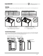
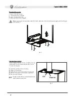
If the unit is enclosed in furniture or mounted alongside, there must be space for removing the casing and
for normal maintenance work.
2.3 Plumbing connections
The heating capacity of the unit should be previously established by calculating the building’s heat requirement ac-
cording to current regulations. The system must be equipped with all its components for it to work properly. It is
advisable to install on-off valves between the boiler and heating system allowing the boiler to be isolated from the
system if necessary.
The safety valve outlet must be connected to a funnel or collection pipe to prevent water flowing out onto
the ground in the event of over-pressure in the heating circuit. If this is not done, and the drain valve trips
and floods the room, the boiler manufacturer is not to be held responsible.
Do not use the water system pipes to earth electrical appliances.
Before installation, carefully wash all the pipes of the system to remove residues or impurities that could affect the
unit’s good working.
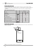
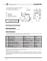
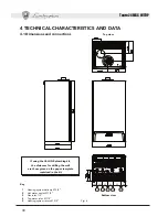
Make the connections to the corresponding connections as shown in fig. 6 in chap. IV and with the symbols on the
unit. A plumbing kit is available on request.
Characteristics of the water system
In the presence of water harder than 25° Fr, we recommend the use of suitably conditioned water in order to avoid
possible scaling in the boiler. Water treatment is indispensable in the case of very large systems or with frequent
introduction of replenishing water in the system. If partial or total emptying of the system becomes necessary under
these conditions, it is advisable to refill it with treated water.
Antifreeze system, antifreeze fluids, additives and inhibitors.
The boiler is equipped with an antifreeze system that turns on the boiler in heating mode when the system delivery
water temperature falls under 6°C. The device will not come on if the electricity and/or gas supply to the unit are cut
off. If it becomes necessary, it is permissible to use antifreeze fluid, additives and inhibitors only if the manufacturer
of these fluids or additives guarantees they are suitable for this use and cause no damage to the heat exchanger
or other components and/or materials of the boiler unit and system. It is prohibited to use generic antifreeze fluid,
additives or inhibitors that are not expressly suited for use in heating systems and compatible with the materials of
the boiler unit and system.
2.4 Gas connection
Before making the connection, ensure that the unit is arranged for operation with the type of fuel available
and carefully clean all the pipes of the gas system to remove any residues that could affect good functioning
of the boiler.
The gas must be connected to the relative connector (see fig. 7) in conformity with current standards, with rigid metal
pipes or with continuous flexible s/steel wall tubing, placing a gas cock between the system and the boiler. Make
sure that all the gas connections are tight.
The capacity of the gas meter must be sufficient for the simultaneous use of all equipment connected to it. The
diameter of the gas pipe leaving the boiler does not determine the diameter of the pipe between the unit and the
meter; it must be chosen according to its length and loss of head, in conformity with current standards.
Do not use the gas pipes to earth electrical appliances.


