background image

Taura 24 MCS W TOP

28

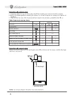
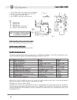
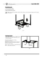
•  Check that the maximum pressure has not changed.
•  Reconnect the pressure compensation tube 

“H”

.

•  Put the protective cap 

“D”

 back on.

•  To end TEST mode, select another mode.

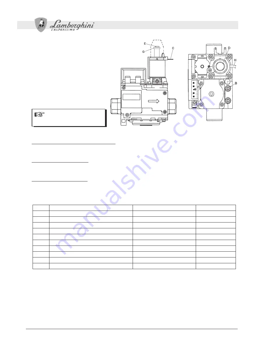
Key


B

 Pressure 

point


C

 Modureg 

cable


D

 Protective 

cap


E


Minimum pressure adjustment


G


Maximum pressure adjustment

Fig. 3

After checking or adjusting the pressure, 
it is mandatory to seal the adjustment 
screw with paint or a specific seal.

Adjusting the maximum heating output

Refer to the Installer parameters menu section

Ignition power adjustment

Refer to the Installer parameters menu section

Installer Parameters menu

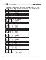
The card is equipped with 10 transparent parameters:  modifiable from Remote Control (Service parameters menu) 

and from the same (Installer Parameters Menu except the last two, 9 and 10):

Num.

Parameters menu

Range

Default

1

Max. heating power

0-100%

100%

2

Gas type selection

0=Natural gas,1=LPG

0=Natural gas

3

Lighting Power

0-60%

50%

4

Heating idle time

0=0minutes, 1=2.5 minutes

1=2.5 minutes

5

Heating pump Post-Circulation

0=0minutes, 1=2.5 minutes

1=2.5 minutes

6

Heating user max. setpoint

30°C, 40°C, 85°C

85°C

7

Hot water user max. setpoint

0=55°C, 1=65°C

0=55°C

8

Boiler shutdown in hot water mode

0=Fixed,1=Tied to setpoint

1=setp.

9

Heating ramp

1-20°C/min

10°C/min

10

Mains Voltage Frequency

0=50Hz,1=60Hz

0=50Hz

Remote Timer Control modification occurs by entering its Service parameters menu (refer to the relevant manual): 
the order and range correspond exactly to that given in the table.
Modification from card occurs as follows. 
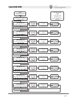
The parameters, named in the previous table P1÷P8, can be displayed and possibly modified from the Installer Pa-
rameters menu by decoding of the LEDs and position, for different time intervals, of the selector. The method for 
accessing, displaying and/or modifying a number of parameters and exiting the menu is described by means of the 
following flow chart.

Содержание Taura 24 MCS W TOP

Страница 1: ...DE GAS CON C MARA ESTANCA PARA AGUA SANITARIA Y CALEFACCI N CALDEIRA MURAL A G S C MARA ESTANQUE PARA PRODU O DE GUA QUENTE SANIT RIA E AQUECIMENTO cod 3540D95 0 ediz 06 2006 AZIENDA CERTIFICATA ISO 9...

Страница 2: ...nit breaks down and or functions poorly deactivate it do not make any attempt to repair it or directly intervene Contact profession ally qualified personnel Any repair replacement of products must onl...

Страница 3: ...iency heat generator for heating and hot water production running on natural or liquefied petroleum gas equipped with an open flue burner with electronic ignition airtight chamber with forced ventilat...

Страница 4: ...s Water system pressure adjustment The filling pressure with the system cold read on the boiler water gauge must be about 1 0 1 5 bar If the system pressure falls to values below the minimum bring it...

Страница 5: ...y under these conditions it is advisable to refill it with treated water Antifreeze system antifreeze fluids additives and inhibitors The boiler is equipped with an antifreeze system that turns on the...

Страница 6: ...city line The connections to the grid must be made with a permanent connection and equipped with a bipolar switch whose contacts have a minimum opening of at least 3 mm interposing fuses of max 3A bet...

Страница 7: ...for coaxial pipes Insert the diaphragm on the aluminium section 60 of the upper flange of the boiler Diaphragm for separate pipes Insert the diaphragm under the flanged air inlet section 80 84 Connec...

Страница 8: ...tion protection air end piece 80 2 Rooftop outlet 80 125 TEE reduction for separate ducts 12 Caution use solely Lamborghini Caloreclima fume suction outlet kits Air suction 80 Air diaphragm Air Fumes...

Страница 9: ...ct WINTER yellow LED on select RESET for 5 seconds LEDs blinking fast for two seconds select WINTER turn the hot water knob ref 2 fig 1 onto minimum for Natural Gas operation or onto maximum for LPG o...

Страница 10: ...00 100 2 Gas type selection 0 Natural gas 1 LPG 0 Natural gas 3 Lighting Power 0 60 50 4 Heating idle time 0 0minutes 1 2 5 minutes 1 2 5 minutes 5 Heating pump Post Circulation 0 0minutes 1 2 5 minut...

Страница 11: ...onds turn to Winter when the 3 LEDs blink fast Selector turned to Reset for 5 seconds turn to Winter when the 3 LEDs blink fast Selector turned to Reset for 5 seconds turn to Winter when the 3 LEDs bl...

Страница 12: ...OFF OFF Natural gas ON BL OFF OFF LPG Red Green Yellow Lighting power OFF OFF OFF 00 06 ON BL OFF OFF 06 13 OFF OFF ON BL 13 21 ON BL OFF ON BL 21 29 OFF ON BL OFF 29 36 ON BL ON BL OFF 36 44 OFF ON B...

Страница 13: ...ated on the meter corresponds to that given in the technical data table in chap 4 Make sure that with no call for heating the burner correctly ignites on opening a hot water tap Check that during heat...

Страница 14: ...hot water temperature to maximum 4 Wait 10 15 minutes for the boiler to stabilize 5 Take the measurement Analyses made with an unstabilized boiler can cause measurement errors Air Fumes Fig 5 Opening...

Страница 15: ...Tap water sensor fault Fault Possible cause Cure Green Yellow Red Heating sensor damaged No circulation of water in the system Air in the system Check the gas flow to the boiler is regular Check the w...

Страница 16: ...ig 6 Top view Bottom view Key 1 Heating system delivery 3 4 2 Hot water outlet 1 2 3 Gas inlet 1 2 4 Tap water inlet 1 2 5 Heating system return 3 4 If using the LEJ LINE plumbing kit the distances fo...

Страница 17: ...amber 20 Burner assembly 21 Main nozzle 22 Burner 26 Combustion chamber insulation 27 Copper exchanger for heating and hot water 28 Fume manifold 29 Fume outlet manifold 32 Heating circulator 34 Heati...

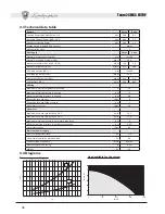
Страница 18: ...nozzles G31 mm 11x0 79 LPG supply pressure G31 mbar 37 0 Pressure at LPG burner G31 mbar 35 0 5 0 LPG delivery G31 kg h 2 00 0 65 Heating Maximum working temperature in heating C 90 Maximum working p...

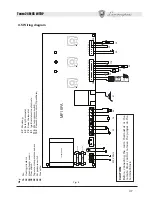
Страница 19: ...FUSE CAUTION Before connecting the room thermostat or the remote timer control remove the jumper on the terminal block Fig 8 Key 16 Fan 32 Heating circulator 34 Heating temp sensor 38 Flow switch 42...

Страница 20: ...per l evoluzione del prodotto The illustrations and data given are indicative and are not binding on the manufacturer LAMBORGHINI reserves the right to make those changes considered necessary for the...

Отзывы: