background image

iXinox 24 C

9

EN

cod. 3541N452EN  -  Rev. 03 - 03/2020

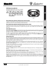
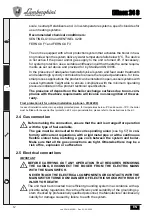
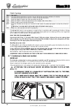
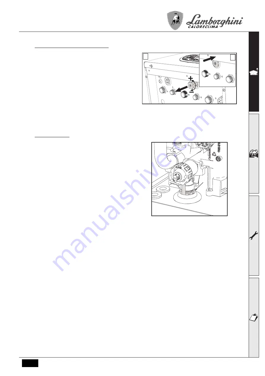
System water pressure adjustment

The filling pressure read on the boiler water gauge
(detail 2 - fig. 16) with system cold must be approx 1.0
bar. If the system pressure falls below minimum va-
lues, the boiler stops and fault 

F37

 is displayed. Pull

out the filling knob (detail 1 - fig. 16) and turn it anti-
clockwise to return it to the initial value. Always close
it afterwards.

Once the system pressure is restored, the boiler will
activate the 300-second air venting cycle indicated on
the display by 

Fh

.

To prevent boiler shutdown, it is advisable to periodi-
cally check the pressure on the gauge with system
cold. In case of a pressure below 0.8 bar, it is advisa-
ble to restore it.

fig. 16- Filling knob

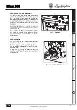
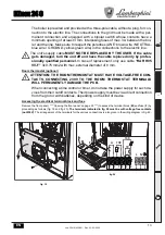
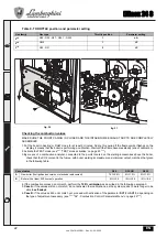
System draining

The drain faucet ring nut is located under the safety
valve inside the boiler.

To drain the system, turn the ring (ref. 1 - fig. 17) coun-
ter-clockwise to open the faucet. Do not use any tools;
use hands only.

To drain only the water in the boiler, first close the
shut-off valves between the system and boiler before
turning the ring.

fig. 17- Safety valve with drain faucet

A

B

1

1

2

1

Содержание iXinox 24C

Страница 1: ...cod 3541N452EN Rev 03 03 2020 iXinox 24 C INSTRUCTIONS FOR USE INSTALLATION AND MAINTENANCE ...

Страница 2: ...e boiler so that it can be consulted by the new owner and or installer Installation and maintenance must be carried out by professionally qualified personnel accor ding to current regulations and the manufactu rer s instructions Incorrect installation or inadequate maintenan ce can result in damage or injury The manufac turer declines any liability for damage caused by errors in installation and u...

Страница 3: ... installation 10 2 3 Plumbing connections 10 2 4 Gas connection 12 2 5 Electrical connections 12 2 6 Fume ducts 14 2 7 Condensate drain connection 20 3 Service and maintenance 21 3 1 Adjustments 21 3 2 Commissioning 32 3 3 Maintenance 33 3 4 Troubleshooting 42 4 Technical data and characteristics 45 4 1 Dimensions and connections 45 4 2 General view 47 4 3 Hydraulic circuit 47 4 4 Technical data t...

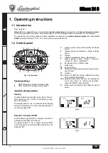
Страница 4: ...button 7 Mode selection button Winter Summer Unit OFF ECO COMFORT 8 Eco Economy or Comfort mode 9 DHW mode 10 Summer mode 12 Multifunction flashing during exchanger protec tion function 13 Heating 14a Burner lit flashing during calibration function and self diagnosis phases 14b Appears when a fault has occurred causing the unit to shut down To restore unit operation press the RESET button detail 6...

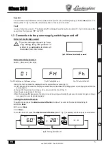
Страница 5: ... power to the boiler During the first 5 seconds the display shows the card software version fig 5 For the following 20 seconds the display will show FH which identifies the heating system air venting cycle with the fan running fig 6 In the next 280 seconds the venting cycle continues with the fan off fig 7 Open the gas valve ahead of the boiler When the message Fh disappears the boiler is ready to...

Страница 6: ...e DHW circuit and the heating system water or drain just the DHW circuit and add a suitable antifreeze to the he ating system as prescribed in sez 2 3 NOTE If the sun symbol does not appear on the display but the multifunction numbers are present the boiler is in Winter mode 1 4 Adjustments Winter summer switchover Press the winter Summer off button detail 7 fig 1 until the display shows the Summe...

Страница 7: ...robe optional is installed the boiler adjustment system works with Sliding Temperature In this mode the heating system temperature is regulated according to weather conditions to ensure high comfort and energy efficiency throughout the year In particular as the outside temperature increases the system delivery temperature de creases according to a specific compensation curve With the Sliding Tempe...

Страница 8: ...emote Timer Control menu and the boiler control panel DHW temperature adjustment Adjustment can be made from the Remote Timer Control menu and the boiler control panel Summer Winter Switchover Summer mode has priority over a possible Remote Timer Control heating demand Eco Comfort selection On disabling DHW from the Remote Timer Control menu the boiler selects Economy mode In this condition the ec...

Страница 9: ...will activate the 300 second air venting cycle indicated on the display by Fh To prevent boiler shutdown it is advisable to periodi cally check the pressure on the gauge with system cold In case of a pressure below 0 8 bar it is advisa ble to restore it fig 16 Filling knob System draining The drain faucet ring nut is located under the safety valve inside the boiler To drain the system turn the rin...

Страница 10: ...ted recess The place of installation must be free of flammable materials objects and dusts or corrosive gases The boiler is arranged for wall mounting and comes as standard with a hooking bracket Wall fixing must ensure stable and effective support for the generator A If the unit is enclosed in a cabinet or mounted alongside there must be sufficient space for removing the casing and for normal mai...

Страница 11: ...d the provisions of EN14868 protection of metallic materials against corrosion The filling water first filling and subsequent replenishment must be clear with har dness below 15 F and treated with suitable chemical conditioners against the ini tiation of corrosion that are not aggressive on metals and plastics do not develop gases and in low temperature systems do not cause proliferation of bacter...

Страница 12: ...st protection kit for outdoor installation optional 013022X0 In case of installation outdoors in a partially protected place for temperatures below 5 C and down to 15 C the boiler must be fitted with the special frost protection kit For proper installation please refer to the instructions in the kit 2 4 Gas connection B Before making the connection ensure that the unit is arranged for operation wi...

Страница 13: ...lacement only use cable HAR H05 VV F 3x0 75 mm2 with max external diameter of 8 mm Room thermostat optional B ATTENTION THE ROOM THERMOSTAT MUST HAVE VOLTAGE FREE CON TACTS CONNECTING 230V TO THE ROOM THERMOSTAT TERMINALS WILL PERMANENTLY DAMAGE THE PCB When connecting a time control or timer do not take the power supply for such de vices from their cutoff contacts Their power supply must be via a...

Страница 14: ...red to the normal level after manual or automatic topping up 3 Manages a solar 3 way valve The contacts are closed when the DHW mode is active Manages a Legionella pump only with b01 2 The contacts are closed when the Legionella protection is running 4 Manages a second heating pump The contacts are closed when the heating mode is active 5 Use as an alarm output warning light goes off The contacts ...

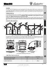
Страница 15: ... to type C10 must be carried out by specialist personnel doing the calcula tions required by current regulations in compliance with the maximum positive pressure of the flue and the boi ler Connection with coaxial pipes fig 21 Examples of connection with coaxial pipes Air Fumes For coaxial connection fit the unit with one of the following starting accessories For the wall hole dimensions refer to ...

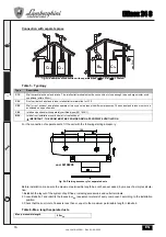
Страница 16: ... position 3 Check that the sum total of losses is less than or equal to the maximum permissible length in tabella 6 Table 6 Max length separate ducts Type Description C1X Wall horizontal exhaust and intake The inlet outlet terminals must be concentric or close enough to be undergo similar wind conditions within 50 cm C3X Roof vertical exhaust and intake Inlet outlet terminals like for C12 C5X Wall...

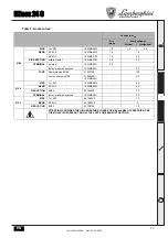
Страница 17: ... 1KWMA85A 2 0 fumes wall with antiwind 1KWMA86A 5 0 FLUE Split air fumes 80 80 010027X0 12 0 Fume outlet only Ø80 010026X0 1KWMA86U 4 0 Ø 60 PIPE 1 m M F 1KWMA89W 6 0 BEND 90 M F 1KWMA88W 4 5 REDUCTION 80 60 041050X0 5 0 TERMINAL fumes wall with antiwind 1KWMA90A 7 0 Ø 50 PIPE 1 m M F 041086X0 12 BEND 90 M F 041085X0 9 REDUCTION 80 50 041087X0 10 ATTENTION CONSIDER THE HIGH PRESSURE LOSSES OF Ø50 ...

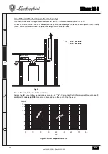
Страница 18: ... and up to 4 m of Ø80 mm flue on the intake with max length of Ø50 and Ø60 flues To use this width follow the instructions below Access the SC menu follow the instructions given in par Sc Combustion Control Parameters Menu on page 29 and bring the parameter SC04 to a value corresponding to the length of the flue used fig 26 Chart for flue parameter choice fig 25 A Ø50 28 m MAX Ø60 78 m MAX max 4 m...

Страница 19: ... EN cod 3541N452EN Rev 03 03 2020 Connection to collective flues fig 27 Examples of connection to collective flues Air Fumes fig 28 Connection examples system C10 and C11 Air Fumes C8X C2X C4X C93 C93 C11 C11 C10 C10 ...

Страница 20: ...ate drain connection IMPORTANT The boiler has an internal trap for draining condensate Install the hose B by pressing it into place Before commis sioning fill the trap with approx 0 5 L of water and connect the hose to the disposal system Drains connected to the drainage system must be resistant to acidic condensate If the condensate drain is not connected to the waste water drainage system a neut...

Страница 21: ...ows 100 and co blinking press the Heating button detail 4 fig 1 until setting and displaying 120 Then press the DHW button detail 2 fig 1 until setting 123 Press the Reset button detail 6 fig 1 once The display shows tS blinking press the Heating button detail 4 fig 1 once The display shows Sc blinking press the Reset button detail 6 fig 1 once The display shows Sc alternating with 01 blinking Pre...

Страница 22: ...fumes with boiler working at maximum and minimum output matches that given in the following table 4 If the combustion values do not match perform the 100 calibration as described in the following paragraph 5 Case A if the values still do not match do not activate other calibrations as the system needs to work longer to be able to self adapt 6 Case B if the values still do not match yet proceed wit...

Страница 23: ...0 calibration automatic Automatic calibration can take place in some cases in the absence of a DHW or heating demand or after a reset due to a fault and is indicated on the display by the flashing flame symbol Loading parameters with BCC KEY The BCC KEY device allows the updating of combustion parameters for boiler type It is used in case of replacement of the PCB of some boiler models To use the ...

Страница 24: ...00 Do not modify the value 85 Absolute Maximum Heating Power b02 4 0 100 Do not modify the value 90 b04 System water pressure protec tion selection 0 Pressure switch 1 Pressure transducer 0 Pressure switch b05 Summer Winter function 0 WINTER SUMMER OFF 1 WINTER OFF 0 Enabled b06 Variable input contact operation selection b01 1 0 Flowmeter off 1 System thermostat 2 Second room ther mostat 3 Warning...

Страница 25: ... b13 Not implemented b01 1 Priority override Deactivation b01 2 0 255 minutes 15 minutes Not implemented b01 3 Priority override Deactivation b01 4 0 255 minutes 15 minutes b14 Pump antiblock operation time 0 20 seconds 5 seconds b15 Flowmeter type selection b01 1 0 Flow 450 imp l 1 Flow 700 imp l 2 Flow 190 imp l 2 Flowmeter 190 imp l No effect on adjustment b01 2 0 Flow 450 imp l 1 Flow 700 imp ...

Страница 26: ...activation temperature during Post Circulation b01 1 0 100 C 50 C Pump deactivation temperature during Post Circulation b01 2 0 100 C 55 C Pump deactivation temperature during Post Circulation b01 3 0 100 C 55 C Pump deactivation temperature during Post Circulation b01 4 0 100 C 55 C P39 Pump activation hysteresis tem perature during Post Circulation b01 1 0 100 C 10 C Pump activation hysteresis t...

Страница 27: ...er b02 2 0 100 100 DHW maximum power b02 3 0 100 94 DHW maximum power b02 4 0 100 100 P49 Comfort1 standby time b01 1 0 100minutes 20 minutes Not implemented b01 2 Not implemented b01 3 Not implemented b01 4 P50 Comfort2 standby time b01 1 0 100 minutes 42 minutes Not implemented b01 2 Not implemented b01 3 Not implemented b01 4 P51 Solar deactivation temperature b01 1 0 100 C 10 C Setpoint deltaT...

Страница 28: ...50 C 43 C Primary exchanger protection temperature b01 3 0 150 C 43 C Primary exchanger protection temperature b01 4 0 150 C 43 C P56 System min pressure value 0 8bar 10 Only for boilers with water pressure sensor 4 bar 10 P57 System nominal pressure value 5 20bar 10 Only for boilers with water pressure sensor 7 bar 10 P58 Exchanger protection interven tion b01 1 0 No F43 1 15 1 15 C second 10 C s...

Страница 29: ...cult starting 9 20 0 Sc03 Ignition power Allows the fan speed to be increased or decreased in the ignition phase in case of difficult starting 16 14 0 Sc04 Flue length Allows the boiler to be arranged according to the width and length of the flue used To be used only with Ø50 or Ø60 flues See fig 26 2 13 0 Sc05 Minimum power calibration Allows the minimum power to be increased if necessary 0 25 0 ...

Страница 30: ...ing or DHW mode and press the Reset button ref 6 fig 1 for 10 seconds The display shows 100 and the text Co flashing press the Heating button ref 4 fig 1 to set and view 120 Then press the DHW button ref 2 fig 1 to set 123 Press the Reset button ref 6 fig 1 once The display shows Ts flashing press the heating button ref 4 fig 1 once The display shows Sc flashing press the reset button once The dis...

Страница 31: ... display the value Press the Reset button to return to the Service Menu Press the Reset button for 10 seconds to exit the card Service Menu or exiting occurs automatically after 15 minutes rE History Reset Press the Winter Summer Off On button for 3 seconds to delete all faults stored in the History Menu the card automa tically exits the Service Menu in order to confirm the operation Press the Res...

Страница 32: ...er the boiler the display will show the software version number and then Fh and FH air venting cycle see cap 1 3 Connection to the power supply switching on and off on page 5 At the end of the FH cycle the winter mode screen fig 8 will appear on the display make the temperature adjustmen ts heating delivery and DHW outlet fig 12 and fig 13 Check if the flue parameter value Sc Combustion Control Pa...

Страница 33: ...any operation wait for these com ponents to cool or else wear suitable gloves To open the boiler casing 1 Partially undo the screws A see fig 33 2 Pull the panel B towards you and release it from the upper fastenings fig 33 Front panel opening BOn this unit the casing also acts as a sealed chamber After any operation in volving opening the boiler carefully check the correct refitting of the front ...

Страница 34: ...re must match that given in the respective tables The condensate evacuation system must be efficient with no leakage or obstructions The trap must be full of water Check the quality of the water in the system Check the condition of the insulation of the exchanger Check the gas connection between the valve and Venturi Replace the burner gasket if damaged At the end of the check always check the com...

Страница 35: ...ews 2 Move the plate heat exchanger back and slide it to the left Remove the heat exchanger as shown in the figure When refitting the plate heat exchanger make sure the arrows indicating HEATING are pointing downwards Circulating pump ABefore carrying out the following instructions it is advisable to protect the room and the boiler s electrical box against accidental water spillage Disconnect the ...

Страница 36: ...he fan connector Disconnect the connector of the ignition electrode connected to the board Drain the water from the boiler heating circuit Extract the flue connection concentric or accessory for separate ducts Remove the fan Remove the clips of the two pipes on the exchanger pump and hydraulic unit Remove the 2 top screws 5 securing the exchanger to the frame fig 41 Loosen the 2 bottom screws 5 se...

Страница 37: ...ead of the valve Undo the 5 screws securing the exchanger cover Undo the 3 screws securing the burner Check the correct distance of the electrodes To clean the exchanger it is advisable to remove the electrode see fig 45 Clean the inside of the exchanger with the accessories indicated in fig 42 Do not use metal brushes which could damage the exchanger 3 5 mm 2 1 ...

Страница 38: ...move the cover of the heat exchanger and the burner see fig 42 Pull out the electrode 1 Rotate the insulating disc 2 and remove it Fan fig 43 Disconnect the power supply and turn off the gas cock ahead of the valve Remove the connector from the fan Remove the clamp 1 and undo the screws 2 Remove the fan electrical connections and then the fan 1 2 3 1 2 3 ...

Страница 39: ...a use the KEY device following the instructions attached to the kit Replacing the electrode and maintenance fig 45 Disconnect the power supply and turn off the gas cock ahead of the valve Electrically disconnect the electrode and remove it by undoing the screws 1 Remove the exchanger cover and remove the burner see fig 42 Clean the electrode see fig 42 Refit the clean or new electrode and secure i...

Страница 40: ...f the gas cock ahead of the valve Remove the diverter valve connector Remove the clip 1 and remove the diverter valve 2 Replacing the water pressure switch ABefore carrying out the following instructions it is advisable to protect the room and the boiler s electrical box against accidental water spillage fig 47 Disconnect the power supply and turn off the gas cock ahead of the valve Remove the con...

Страница 41: ...y and turn off the gas cock ahead of the valve Remove the diverter valve connector Close the cold water inlet and turn on the DHW system faucets Release the fork 4 and remove the flowmeter assembly 5 The flowmeter components can thus be cleaned see fig 49 and fig 50 or replaced fig 48 Flowmeter 1 Flow rate restrictor 2 Fan 3 Filter 4 Clip 5 Flowmeter Wash the filter with clean water fig 49 Lubrica...

Страница 42: ...ion it is sufficient to press the reset button detail 6 fig 1 for 1 second or use the RESET on the remote timer control optional if installed if the boiler does not restart it is necessary to firstly eliminate the fault Other faults cause temporary shutdowns marked with the letter F which are automatically reset as soon as the value returns within the boiler s normal working range fig 51 fig 52 Ma...

Страница 43: ...s Trap blocked Check the trap and clean it if necessary F07 F14 F15 A07 High fume temperature The fume probe detects an excessive temperature Check the exchanger Check the flue gas probe Check the flue material parameter F08 A08 Overtemperature protection intervention Heating sensor damaged Check the correct positioning and operation of the heating sensor and replace it if necessary No water circu...

Страница 44: ...de replace it if necessary After replacement repeat the 100 calibration Recirculation of fumes inside the boiler Check the tightness of the flue pipe and the seal of gaskets Calibration procedure not com pleted Poor primary circuit circulation or poor dissipation during calibration Reset the fault Turn on the hot water faucet and wait for the flame to stop flashing about 2 minutes F61 A61 Controll...

Страница 45: ...ons and connections 7 Gas inlet Ø 3 4 8 DHW outlet Ø 1 2 9 Cold water inlet Ø 1 2 10 System delivery Ø 3 4 11 System return Ø 3 4 A6 Condensate discharge connection fig 54 Front view fig 55 Side view fig 56 Top view fig 57 Bottom view 250 110 210 210 160 115 45 65 66 66 65 113 10 8 7 9 11 A6 44 80 ...

Страница 46: ...od 3541N452EN Rev 03 03 2020 Metal template code 046049X0 and wall holes fig 58 fig 59 Ø3 4 Ø1 2 Ø1 2 Ø1 2 Ø3 4 45 65 66 66 65 113 Ø110 120 mm 775 658 89 Ø3 4 Ø1 2 Ø1 2 Ø1 2 Ø3 4 45 65 66 66 65 113 847 658 161 100 81 Ø100 ...

Страница 47: ...ature sensor 193 Trap 194 DHW exchanger 196 Condensate tray 350 Burner Fan assembly fig 61 Hydraulic circuit 8 DHW outlet 9 Cold water inlet 10 System delivery 11 System return 14 Safety valve 32 Heating circulating pump 34 Heating temperature sensor 36 Automatic air vent 42 DHW temperature probe 56 Expansion vessel 74 System filling cock 95 Diverter valve 114 Water pressure switch 136 Flow meter ...

Страница 48: ... Pmin 50 30 C 107 5 Efficiency 30 109 8 Gas supply pressure G20 mbar 20 Max gas flow G20 m3 h 2 65 Min gas flow G20 m3 h 0 53 CO2 G20 9 0 8 Gas supply pressure G31 mbar 37 Max gas flow G31 kg h 1 94 Min gas flow G31 kg h 0 39 CO2 G31 10 0 8 NOx emissions class 6 NOx Max working pressure in heating bar 3 PMS Min working pressure in heating bar 0 8 Max heating adjustment temperature C 90 tmax Heatin...

Страница 49: ...ŵĞ ΎΎͿ ƚ ĨƵůů ůŽĂĚ ƚ ƉĂƌƚ ůŽĂĚ Ŷ ƐƚĂŶĚďLJ ŵŽĚĞ ƚĂŶĚďLJ ŚĞĂƚ ůŽƐƐ ŐŶŝƚŝŽŶ ďƵƌŶĞƌ ƉŽǁĞƌ ĐŽŶƐƵŵƉƚŝŽŶ ŶŶƵĂů ĞŶĞƌŐLJ ĐŽŶƐƵŵƉƚŝŽŶ ŽƵŶĚ ƉŽǁĞƌ ůĞǀĞů ŵŝƐƐŝŽŶƐ ŽĨ ŶŝƚƌŽŐĞŶ ŽdžŝĚĞƐ ĞĐůĂƌĞĚ ůŽĂĚ ƉƌŽĨŝůĞ tĂƚĞƌ ŚĞĂƚŝŶŐ ĞŶĞƌŐLJ ĞĨĨŝĐŝĞŶĐLJ ĐůĂƐƐ ĨƌŽŵ н ƚŽ Ϳ ĂŝůLJ ĞůĞĐƚƌŝĐŝƚLJ ĐŽŶƐƵŵƉƚŝŽŶ ŶŶƵĂů ĞůĞĐƚƌŝĐŝƚLJ ĐŽŶƐƵŵƉƚŝŽŶ tĂƚĞƌ ŚĞĂƚŝŶŐ ĞŶĞƌŐLJ ĞĨĨŝĐŝĞŶĐLJ ĂŝůLJ ĨƵĞů ĐŽŶƐƵŵƉƚŝŽŶ ŶŶƵĂů ĨƵĞů ĐŽŶƐƵŵƉƚŝŽŶ dƌĂĚĞŵĂƌŬ D KZ E KZ D ŽŶĚĞŶ...

Страница 50: ...re probe 44 Gas valve 72 Room thermostat not supplied 81 Ionization ignition electrode 95 Diverter valve 114 Water pressure switch 136 Flowmeter 138 External probe optional 139 Remote timer control optional 186 Return sensor 191 Fume temperature sensor 288 Frost protection kit A ON OFF switch configurable 0 0 0 5 1 0 1 5 2 0 2 5 3 0 3 5 4 0 4 5 5 0 5 5 6 0 6 5 7 0 7 5 8 0 0 0 1 0 2 0 3 0 4 0 5 0 6...

Страница 51: ...nect the vol tage free contacts of the zones to terminals 1 2 and the timer control to terminals 5 6 ALL CONNECTIONS TO THE TERMINAL BLOCK MUST BE WITH VOLTAGE FREE CONTACTS NOT 230V LC32 72 139 1 2 3 4 5 6 138 A L N X03 X04 X05 X06 X07 X08 X02 X01 114 34 42 16 44 191 136 95 186 1 1 1 1 1 1 1 1 X08 11 X08 10 X08 7 X08 6 X08 2 X08 1 X09 X11 X08 14 X08 12 X08 13 X08 9 X08 8 X01 4 X01 7 X01 6 X01 5 X...

Страница 52: ...108 BRUCIATORI CALDAIE MURALI E TERRA A GAS GRUPPI TERMICI IN GHISA E IN ACCIAIO GENERATORI DI ARIA CALDA TRATTAMENTO ACQUA CONDIZIONAMENTO iÊ Ê Ì Þ VIA ÇnÉ ÎÇ047 Ê Ê6 Ê Ê ...

Отзывы: