- 24
-
•
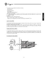
The room where the burner is housed should be kept clean at all times, and there should be no volatile substances in the
vicinity, substances which could be sucked into the fan and could block up the internal ducts of the burner or combustion
head. Dust can be extremely harmful, particularly when it gets onto the fan blades as this can reduce ventilation and
lead to pollution during combustion. Dust can also build up on the rear of the flame stability disk inside the combustion
head, leading to a poor air-fuel mixture.
•
The burner must be fed with the type of fuel for which it was designed, as indicated on the data plate and in the technical
characteristics given in this manual. The fuel feed line must be sealed and must be of the rigid variety, with an interposed
metal expansion coupling with either a flange joint or a threaded joint. Furthermore, the feed line must be equipped with
all the adjustment and safety devices required by the local regulations in force. Particularly ensure that no foreign bodies
get into the feed line during installation.
•
Ensure that the electrical power supply used conforms to the technical characteristics indicated on the data plate and in
this manual. The burner must be connected to an effective system earthed in accordance with the current regulations.
Should there be any doubts, the verification should be made by qualified persons.
•
Never exchange neutral and phase wires.
•
The burner can be connected up to the mains supply using a plug connection only if the latter is of the kind that does
not allow neutral and phase wires to be reversed. Install a main switch for the heating system on the control panel, as
required by current regulations.
•
The entire electrical system, and in particular cable cross-sections, should conform to the maximum absorbed capacity
indicated on the appliance data plate and in this manual.
•
Should the burner’s mains cable be found faulty, it must only be replaced by qualified persons.
•
Do not touch the burner with parts of the body which are wet or when in bare feet.
•
Do not pull (stretch) the mains cables and keep them well away from heat sources.
•
The length of the cables used must enable the burner to be opened, as well as the boiler door.
•
The electrical connections must be made exclusively by qualified experts and the relative regulations in force must be
scrupulously applied.
•
After removing the packaging materials, check the content integrity and make sure that no damages have occured during
transportation. In case of doubt, do not use the burner and contact the supplier. The packaging material (wooden cages,
cartons, plastic bags, foam, clips, etc...) are potential sources of pollution and danger, if left lying around; they should be
collected up and disposed of in the correct way (in a suitable place).
DESCRIPTION
These are mechanically atomised, light oil burners. The path of the air flow has been studied to obtain a high pressure
curve with a uniform and linear air flow from the fan. The dosage of air in the combustion is obtained with a double con-
trol: one on the choke line with movement of the deflector disk on a conical trunk head, and the other with a shutter on
the fan air intake. This system permits us to obtain optimum conditions of pressure/air flow in the entire working area of
the burner, in order to obtain combustion with a low excess of air, high effective output and a high energy level with a low
level of pollutants, CO and Nox. The air shutter is closed completely when the burner is turned off, to limit the dispersion
of heat from the burner during rest periods. It is motorised with a electric air flow control with three positions: closed-open
first flame, open second flame.
All of the components are protected by an elegant case, which also serves as a good silencer. The function is automatic
with surveillance of the flame by means of a photo resistance sensor. There is an auto-suction pump with one or two tubes,
an incorporated bypass and electromagnetic valve. The burners may be inspected completely, which makes for rapid and
easy control and maintenance.
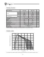
Types ECO 50/2 and ECO 70/2 with double choke, with reduced output start-up and high/low flame function.
Содержание ECO 50/2
Страница 2: ......
Страница 21: ...21 ITALIANO...
Страница 39: ...39 ENGLISH...
Страница 57: ...57 FRAN AIS...
Страница 75: ...75 DEUTSCH...
Страница 93: ...93 ESPA OL...
Страница 100: ...100 fi BRM CRT F FA FR IG fi fi Ima fi MA MB MS RM RT fi SB TC TMF fi 2 fi TR VE1 1 fi VE2 2 fi A B D C D...
Страница 105: ...105 A fi A ECO 50 2 ECO 70 2 A B fi fi fi 1 fi fi max fi fi 1 fi fi 2 fi 2 fi fi SQN 70...
Страница 106: ...106 1 fi fi fi fi fi fi 2 F P VE1 1 VE2 2 G1 1 G2 2 A fi fi fi fi fi fi B fi VE1 G1 fi fi fi fi fi...
Страница 108: ...108 fi fi fi fi fi fi fi fi fi fi 0 0 5...
Страница 109: ...109 fi fi fi fi 5 6 fi fi fi fi 5 6...
Страница 110: ...110 a b a b c a fi b c a b c fi a b a b a b c fi a b c fi fi a b a b fi fi...
Страница 111: ......


