10
2.4
Making the DC Output Connections
Before making any of DC output connections make sure you have read and fully understand the DC Connection
Procedure below.
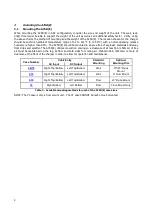
Select proper size for the DC wiring from the wire size table on the previous page. If the
distance between the unit’s DC output and the DC load exceeds 10 feet, use the Power Cable Guide below to
minimize the voltage drop across the wire distance.
Power Cabling Guide
Use the following formulas and table to determine proper wire size for minimal voltage drop.
Table of Conventions
CMA
= Cross section of wire in circular MIL area
A
= Ultimate drain in amperes
LF
= Conductor loop feet
MaxAmp = Maximum allowable amperes for given voltage drop
AVD
= Allowable voltage drop
K
= 11.1 for commercial (TW) copper wire (KS5482-01)
= 7.4 for aluminum (KS20189)
Calculating Wire Size Requirements
AVD
K
LF
A
CMA
×
×
=
Calculating Current Carrying Capacity of Wire
K
LF
AVD
CMA
MaxAmp
×
×
=
DC Connection Procedure
To prevent the DC circuit breaker from tripping when connecting the battery, connections should be done in the
following order.
1.
Turn off the unit’s AC and DC circuit breakers.
2.
Connect AC line to the unit’s input terminals as described in
Section 2.3 Making the AC Input Connections
.
3.
Connect the battery cables to the unit’s DC output terminals.
OBSERVE PROPER POLARITY
.
4.
Energize the power supply by turning on the unit’s AC breaker. This will charge the capacitors inside the
unit and eliminate heavy arcing when the battery is connected.
5.
After about 30 seconds, turn on the DC breaker
SIZE
(AWG)
AREA
CIR.MILS
SIZE
(MCM)
AREA
CIR.MILS
18
1620
250
250000
16
2580
300
300000
14
4110
350
350000
12
6530
400
400000
10
10380
500
500000
8
16510
600
600000
6
26240
700
700000
4
41740
750
750000
3
52620
800
800000
2
66360
900
900000
1
83690
1000
1000000
0
105600
1250
1250000
00
133100
1500
1500000
000
167800
1750
1750000
0000
211600
2000
2000000
Table 7 - Wire Size/Area Table
Содержание A75D
Страница 2: ......


