background image

37 
 

Appendix F: Manufacturer’s Extended Parts Warranty 

(T

HIS IS YOUR 

W

ARRANTY IF YOU HAVE PURCHASED THE 

E

XTENDED 

P

ARTS 

W

ARRANTY AS SHOWN ON OUR INVOICE TO YOU OR IF YOU 

PURCHASE THE 

E

XTENDED 

P

ARTS 

W

ARRANTY ANYTIME DURING THE FIRST 

12

 MONTHS AFTER THE DATE OF OUR INVOICE

All La Marche Manufacturing Co. equipment has been thoroughly tested and found to be in proper operating condition upon 
shipment from the factory.  Any part or parts of the equipment (except protective devices, DC connectors and other wear-
related items) that prove defective within a one (1) year period from the date of our invoice to you shall be replaced without 
charge providing such defect, in our opinion, is due to faulty material or workmanship and not caused by tampering, abuse, 
misapplication or improper installation.  Labor and parts are covered during this one (1) year period.   

For the next four (4) years after the expiration of the one-year warranty, on a parts replacement only basis, 
any part or parts of the equipment (except protective devices, DC connectors and other wear-related items) 
that prove defective within the additional four (4) year period shall be replaced providing such defect, in our 
opinion,  is  due  to  faulty  material  or  workmanship  and  not  caused  by  tampering,  abuse,  misapplication  or 
improper installation. During this four (4) year period, the warranty covers parts replacement only, no labor or 
other  services  are  provided  by  La  Marche,  nor  is  La  Marche  obligated  to  reimburse  the  owner  or  any  other 
person for work performed. If you return the equipment to our factory (freight prepaid), we will repair and 
cover parts and labor. 

Should a piece of equipment require major component replacement or repair during the extended warranty period, these can 
be handled in one of three ways: 

1.


If  the  Purchaser  elects  to  take  the  responsibility  of  repairing  the  equipment  and  requests  replacement  part(s), 
Purchaser or Sales Representative must contact Factory for return authorization and a purchase order must be issued. 
Replacement part(s) will be promptly shipped and invoiced. After the defective part(s) are returned and inspected at 
the Factory, if the defect(s) were due to faulty material or workmanship, credit will be issued. 

2.


The equipment can be returned to the La Marche factory to have the inspections, parts replacements and testing 
performed by factory personnel. Should it be necessary to return a piece of equipment or parts to the factory, the 
customer or sales representative must obtain authorization from the factory. If upon inspection at the factory, the 
defect was due to faulty material or workmanship, all repairs will be made at no cost to the customer under the 
Extended Warranty. Transportation charges or duties shall be borne by Purchaser. 

3.


If the purchaser elects not to return the equipment to the factory and wishes a factory service representative to make 
adjustments and/or repairs at the equipment location, La Marche's field service labor rates will apply. A purchase 
order to cover the labor and transportation cost is required prior to the deployment of the service representative. 

In  accepting  delivery  of  the  equipment,  the  purchaser  assumes  full  responsibility  for  proper  installation,  installation 
adjustments and service arrangements. Should minor adjustments be required, the local La Marche sales representative should 
be contacted to provide this service only. 

All sales are final.  Only standard La Marche units will be considered for return. A 25% restocking fee is charged when return 
is factory authorized. Special units are not returnable. 

In no event shall La Marche Manufacturing Co. have any liability for consequential damages, or loss, damage or expense 
directly or indirectly arising from the use of the products, or any inability to use them either separately or in combination with 
other equipment or materials, or from any other cause. In addition, any alterations of equipment made by anyone other than 
La Marche Manufacturing Co. renders this warranty null and void. 

La  Marche  Manufacturing  Co.  reserves  the  right  to  make  revisions  in  current  production  of  equipment,  and  assumes  no 
obligation to incorporate these revisions in earlier models. 

The  failure  of  La  Marche  Manufacturing  Co.  to  object  to  provisions  contained  in  customers'  purchase  orders  or  other 
communications shall not be deemed a waiver of the terms or conditions hereof, nor acceptance of such provisions. 

THE ABOVE WARRANTY IS EXCLUSIVE, SUPERSEDES AND IS IN LIEU OF ALL OTHER WARRANTIES, EXPRESSED 
OR IMPLIED, INCLUDING ANY IMPLIED WARRANTY OF MERCHANTABILITY OR FITNESS. NO PERSON, AGENT 
OR DEALER IS AUTHORIZED TO GIVE ANY WARRANTIES ON BEHALF OF THE MANUFACTURER, OR TO ASSUME 
FOR THE MANUFACTURER ANY OTHER LIABILITY IN CONNECTION WITH ANY OF ITS PRODUCTS UNLESS MADE 
IN WRITING AND SIGNED BY AN OFFICIAL OF THE MANUFACTURER. 

Содержание A36D Series

Страница 1: ...D Series Controlled Ferroresonant Rectifier Power Supply Installation and Operation Manual 106 Bradrock Dr Des Plaines 60018 1967 Tel 847 299 1188 Fax 847 299 3061 CPN 129389 Instruction Drawing Number P25 LA36DSERIES 2 Revision A07 Rev Date 12 19 ECN 22429 ...

Страница 2: ...ome in contact with any internal components Do not operate this charger outside the input and output ratings listed on the charger nameplate Do not use this charger for any purpose not described in the operation manual Mechanical Safety This charger or parts of the charger may get very hot during normal operation use care when working nearby Do not expose equipment to rain or snow Always install i...

Страница 3: ...rger sent back for evaluation and repair CAUTION Failure to properly file a claim for shipping damages or provide a copy of the claim to La Marche may void warranty service for any physical damages reported for repair Returns for Service Save the original shipping container If the product needs to be returned for service it should be packaged in its original shipping container If the original cont...

Страница 4: ... Alarm Connections 10 2 4 1 Alarm Connection Procedure 11 2 4 2 Understanding the Alarms 11 2 5 External Temperature Compensation Option 11W 11Y 13 2 6 Load Sharing 13 2 7 Remote Equalize 14 2 8 Remote Voltage Sensing 14 2 9 DNP 3 0 Modbus SCADA Interface Option 21P 21Q 15 2 10 Battery Side Alarm Sensing Option 565 15 3 Operation 16 3 1 Starting the A36D 16 3 1 1 Checking the Installation 16 3 1 2...

Страница 5: ...osure Bolt Pattern 5 Figure 2 9E Enclosure Bolt Pattern 5 Figure 3 4D Enclosure Bolt Pattern 5 Figure 4 33E Enclosure Bolt Pattern 5 Figure 5 33 Enclosure Bolt Pattern 5 Figure 6 A36D Enclosure Footprint 6 Figure 7 Input Terminals Connection Schematic 240VAC Input Shown 7 Figure 8 User Connections to Alarm Contacts on S2A 198 Board 10 Figure 9 S2A 341S Display Control Board 10 Figure 10 Example Co...

Страница 6: ...or 480VAC Understanding the Model Number The A36D model number is coded to describe the options that are included Find the model number on the nomenclature nameplate of the charger Then follow the chart to determine the configuration of your battery charger Optional Accessories Included in the Charger This charger may have been outfitted with a number of optional accessories or option packages To ...

Страница 7: ...tore the value and step back The BACK button will not save the change and will go a step back At any point the settings menu can be exited with or without saving the settings Float Equalize Voltage Advanced Settings Float Voltage Equalize Timer Settings Equalize Voltage o Equalize Timer Mode Alarm Settings o Equalize Timer Hours Advanced Alarm Settings Alarm Thresholds o Alarm Delays o Low Current...

Страница 8: ... Output Voltage Frequency Ampere Rating 10 ADC 12 ADC 15 ADC 20 ADC 25 ADC 30 ADC 50 ADC 12 VDC 60 Hz 39 Case 39 Case 39 Case 33 Case 33 Case 45 lbs 50 lbs 54 lbs 78 lbs 99 lbs 20 4 kg 22 7 kg 24 5 kg 35 4 kg 44 9 kg 50 Hz 33 Case 109 lbs 49 4 kg 24 VDC 60 Hz 39 Case 39 Case 39 Case 39 Case 33 Case 33 Case 33 Case 50 lbs 54 lbs 58 lbs 64 lbs 99 lbs 115 lbs 130 lbs 22 7 kg 24 5 kg 26 3 kg 29 kg 44 ...

Страница 9: ...399 6 kg 48 VDC 60 Hz 9D Case 9D Case 72 Case 72 Case 43 Case 44 Case 44 Case 260 lbs 286 lbs 528 lbs 572 lbs 755 lbs 900 lbs 1193 lbs 117 9 kg 129 7 kg 239 5 kg 259 5 kg 342 5 kg 408 2 kg 541 1 kg 50 Hz 9D Case 9E Case 72 Case 72 Case 43 Case 44 Case 44 Case 287 lbs 315 lbs 582 lbs 630 lbs 832 lbs 992 lbs 1315 lbs 130 2 kg 142 9 kg 264 kg 285 8 kg 377 4 kg 450 kg 596 5 kg Table 2 Case Type and We...

Страница 10: ...er in order to allow for operation and maintenance The bolts or screws used to secure the charger should be sufficient length to assure a vibration free mounting The preferred fastener is a machine bolt backed with a flat washer lock washer and nut All hardware should be corrosion resistant Enclosure Number Cable Entry Standard Mounting Optional Mounting Kits AC Input DC Output 4D Left Top Back Ri...

Страница 11: ...ger on the rack locate the conduit entrances and assure the knockouts on the top sides or bottom of the charger are accessible after the charger is rack mounted To rack mount the A36D first mount the charger onto the rack mounting brackets using the hardware supplied Second install the brackets onto the rack Provide at minimum 6in 152mm of air space above and below to allow for cooling Figure 2 9E...

Страница 12: ...anchor bolts into the floor Place the charger on the bolts add appropriate mounting hardware and tighten securely The figure below shows the footprint and the bolt size of each A36D enclosure style All dimensions are in inches Case Size A B Bolt Size 43 11 5 12 3 8 44 22 17 06 3 8 72 25 75 17 5 1 4 Figure 6 A36D Enclosure Footprint ...

Страница 13: ...h the size of the AC protection used in charger Breaker Size Fuse Size Amps AWG Minimum Wire Size Requirement for Customer Connection AWG Minimum Wire Size for Equipment Grounding 3 14 14 5 14 14 10 14 14 15 14 14 20 12 12 25 10 12 30 10 10 40 8 10 50 8 10 60 6 10 70 6 8 80 4 8 90 4 8 100 4 8 125 2 6 150 1 6 175 1 0 6 200 2 0 6 250 4 0 4 300 250 MCM 4 400 400 MCM 2 500 600 MCM 2 Table 5 AC DC Grou...

Страница 14: ...S20189 Calculating Wire Size Requirements AVD K LF A CMA Calculating Current Carrying Capacity of Wire K LF AVD CMA MaxAmp DC Connection Procedure To prevent the DC circuit breaker from tripping when connecting the battery connections should be done in the following order 1 Make sure that the incoming voltage to the charger is turned off 2 Turn off open the charger s AC and DC circuit breakers 3 C...

Страница 15: ...an 5 seconds the Summary alarm relay will activate if the corresponding alarm is included in the Summary alarm The HVSD alarm is default set to trigger after 20 seconds When an alarm activates the specific indicator on the front panel will light any connected remote annunciators will activate and the display will cycle through all active alarms All alarm contacts for the S2A 198 relay board are de...

Страница 16: ...ds to the NC and C contacts of the desired alarm EXAMPLE A customer wants a green lamp to be illuminated at all times and wants a red lamp to illuminate and a speaker to sound when the Summary alarm triggers The customer would make the connections to the NC and C contacts on one set of the Summary relay contacts between the speaker and a power supply On the other set of Summary relay contacts the ...

Страница 17: ...ARM will trigger and the red OPEN DC PROTECTION LED will turn on if the output DC breaker fuse has been opened In the case the DC protection is opened the bottom line of the display will read OPEN DC PROT AC POWER FAIL ALARM will trigger the green AC ON LED will turn off and the red AC FAIL LED will turn on when the AC power to the charger is lost The alarm will automatically reset when AC power i...

Страница 18: ... overall ambient temperature changes if the batteries and charger are in the same room The accuracy of temperature compensated charging can be greatly enhanced by using an optional remote temperature probe directly on the battery Option 11W 11Y Option 11W includes a 24 foot long temperature probe and Option 11Y includes a 100 foot long temperature probe With either option approximately two feet of...

Страница 19: ...w the same procedure for setting the Equalize voltage 2 7 Remote Equalize A terminal is provided on charger RE for a Remote Equalize function The charger may be remotely forced into Equalize by connecting the RE terminal on TS 5 terminal as shown on the figure above to negative DC bus Caution Damage to the unit will result if the Remote Equalize Terminals are shorted to any other AC or DC voltage ...

Страница 20: ...le between the port on the communication board and the port on the computer For more details on connection instructions as well as operation instructions refer to the DNP 3 0 Modbus SCADA Interface instruction manual included with the A36D The DNP 3 0 Modbus instruction manual is also available online at http www lamarchemfg com 2 10 Battery Side Alarm Sensing Option 565 The optional battery volta...

Страница 21: ... on output current rating 5 Overload Reset 5 of the Overload threshold Current Limit 115 of nominal output current 5 High DC Voltage 2 45 V C 1 60 V C 5 High DC Voltage Reset 5 of the High DC Voltage threshold High Voltage Shutdown 2 50 V C 1 65 V C 20 Battery End of Discharge 1 75 V C 1 10 V C 5 End of Discharge Reset 5 of the End of Discharge threshold Equalize Timer Mode Automatic Equalize Off ...

Страница 22: ... is standard to the A36D The digital control board is a more attractive and user friendly option with many additional features over the standard LED analog control board Figure 13 A36D Front Panel After the A36D has completed the startup sequence AC ON and FL green LED indicators on the front panel will be lit additional indicators will be lit according to the system s status as pictured above The...

Страница 23: ...e 1 7 Day Auto EQ Mode 1 is an automatic Equalize cycle that activates every 7 days The length of the Equalize cycle is determined by the timer setting The length of the timer is 8 hours by default After the timer cycles to zero the charger will automatically return to Float Mode Equalize Mode will restart again after 7 days Mode 2 14 Day Auto EQ Mode 2 is an automatic Equalize cycle that activate...

Страница 24: ...is factory adjusted for a higher voltage Returning to default will return the charger to a 24L voltage setting 3 4 1 1 Float Eq Voltage The Float Eq Voltage submenu provides access to change the Float Voltage and Equalize Voltage Settings Float Voltage Setting The float voltage adjustment is set at the factory at 2 17 V C LA 2 25 V C VRLA or 1 4 V C NC The Float voltage increments by 0 1V Select F...

Страница 25: ...e charger which are not included in the basic Settings Menu The Advanced Settings Menu is divided into 7 submenus Equalize Timer Settings Advanced Alarm Settings Temperature Compensation Ground Detection Alarm Enable Communication Settings LCD Settings and Return to Defaults Equalize Timer Settings The Equalize Timer Settings submenu provides access to the change the Equalize Timer Mode and Equali...

Страница 26: ...ed for Summary Alarm AC Power Fail Alarm Low Current Alarm Low Voltage Alarm High Voltage Alarm Positive Ground Alarm and Negative Ground Alarm If any alarm contacts are set to latch the alarm will not clear until the ALARM RESET button is pressed even if the alarm condition returns to normal By default no alarms are set as latching except for High Voltage Shutdown HVSD All other alarms will clear...

Страница 27: ...tion Modbus Type TCP TCP Serial Modbus Address 1 1 247 Modbus Baud Rate 9600 1200 2400 4800 9600 19200 38400 Setting available only if Modbus Type is set to Serial Modbus Parity Type None None ODD EVEN Setting available only if Modbus Type is set to Serial Read Only Mode No No Yes NOTE For TCP settings see SCADA Interface instruction manual included with the charger Chargers with MODBUS RTU Option...

Страница 28: ...e user to run a basic lamp test on the A36D After selecting this menu press the ENTER button to light all of the LEDs on the display membrane To end the LED test press back NOTE Any additional LEDs on auxiliary boards will not be affected by this LED test 3 5 2 Test Relays The test relays menu allows the user to test the functionality of the alarm relay contacts The menu allows for each contact to...

Страница 29: ...put voltage adjustments Raising Output Voltage with Batteries Connected Note the DC load prior to making adjustments Increase the Float Equalize output voltage setting via Settings Menu as shown on Section 3 4 1 1 The output current will rise and gradually drop to its steady load current Meanwhile the output voltage will slowly rise to its setpoint Once steady repeat incrementing the output voltag...

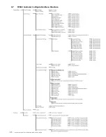
Страница 30: ...25 Submenu is dependent on communications option included in charger 3 7 TPSD2 Customer Configuration Menu Structure ...

Страница 31: ... the desired battery type defaults refer to Section 3 4 1 2 for procedure and Section 3 1 for default values Q If equipped with alarm contacts can the alarm contact reference on the charger schematic be used for determining connections A Not completely The charger schematic for a charger with the option included will show an alarm relay board with contact indication However all the contacts are sh...

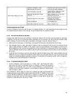
Страница 32: ...rly 1 Confirm air vents are open Remove dust and debris from interior of unit 2 Verify all connections are tight 3 Perform a visual inspection on all internal components 4 Check front panel meters for accuracy and LED operation 5 Measure the output ripple Without interrupting a live system measure ripple at the DC output terminals of the charger with a True RMS multimeter in the AC voltage setting...

Страница 33: ...he problem is found to be located in the printed circuit boards the board should be replaced No attempt should be made to repair circuit boards in the field La Marche Service Technicians are available to help with troubleshooting or with scheduling charger service When calling for a service inquiry or for troubleshooting assistance be sure to have all of the following information on hand 1 Equipme...

Страница 34: ...e Connections on DC Breaker Inspect DC cable connections and assure proper insertion Incorrect Battery Connected Measure battery voltage and verify against charger nameplate 3 Low Output Voltage or Current No AC Input Voltage Applied Measure and confirm input voltage Incorrect Battery Connected Measure battery voltage and verify against charger nameplate Incorrect Damaged or Loose Cable Harness Co...

Страница 35: ...one terminal of the input to one terminal of the output Meter should not indicate If the meter reads full scale deflection this indicates an AC DC short During shipping an AC wire may rub against the DC lugs terminals etc and cause a short These problems may be eliminated by being very careful in inspecting the wiring to assure the AC wires are not touching the DC wiring 3 Check the input terminal...

Страница 36: ... resistance in either direction indicating an open circuit 4 All diodes must be checked in the event that more than one diode is defective 5 If the diode is defective remove the defective diode from the heatsink and replace with a new diode 5 3 4 Checking Capacitors 1 When checking capacitors assure all AC power is turned off and battery is disconnected from charger Check capacitors with DC voltme...

Страница 37: ...ted to a battery which is heavily discharged and recharge it without clearing any protective devices ENVIROMENTAL Audible Noise Less than 65dBA at any point 5 feet from any vertical surface Operating Temperature 32 to 122 F 0 to 50 C Storage Temperature 40 to 185 F 40 to 85 C Relative Humidity 0 to 95 non condensing Cooling Convection cooled Shock The battery charger in its shipping container with...

Страница 38: ...36D 15 24V 15 5 7 5 A36D 20 24V 20 6 7 10 A36D 25 24V 25 8 4 4 2 4 8 15 7 5 7 5 4 2 4 6 7 5 A36D 30 24V 30 10 5 5 8 15 7 5 7 5 5 5 5 7 5 A36D 50 24V 50 16 8 8 4 9 7 30 15 15 8 4 9 2 15 A36D 75 24V 75 25 2 12 6 14 5 40 20 20 12 6 13 8 20 A36D 100 24V 100 33 6 16 8 19 4 40 20 20 16 8 18 3 20 A36D 150 24V 150 50 5 25 2 29 1 70 35 35 25 2 27 5 35 A36D 200 24V 200 67 33 6 38 8 80 40 40 33 6 36 7 40 48 ...

Страница 39: ...C Supply Breaker BD3 240 208V C3 480V 5G3 380V 24 Volt Systems A36D 200 24V 200 16 9 19 5 25 8 5 15 10 7 15 A36D 300 24V 300 25 4 29 3 35 12 7 20 16 20 A36D 400 24V 400 33 9 39 1 50 16 9 25 21 4 25 48 Volt Systems A36D 200 48V 200 33 9 39 1 50 16 9 25 21 4 25 A36D 300 48V 300 50 8 58 6 80 25 4 40 32 1 40 A36D 400 48V 400 67 7 78 1 100 33 9 50 42 8 50 ...

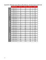
Страница 40: ... 46 150 A36D 12 24V 372 316 56 191 A36D 15 24V 466 396 70 241 A36D 20 24V 621 528 93 321 A36D 25 24V 776 660 116 402 A36D 30 24V 932 792 140 482 A36D 50 24V 1553 1320 233 803 A36D 75 24V 2329 1980 349 1205 A36D 100 24V 3106 2640 466 1606 A36D 150 24V 4659 3960 699 2410 A36D 200 24V 6212 5280 932 3213 48 Volt Systems A36D 10 48V 621 528 93 312 A36D 12 48V 745 633 112 383 A36D 15 48V 932 792 140 382...

Страница 41: ...during the first year If the Extended Warranty is purchased the parts required for repair will also be at no cost but La Marche will notify the Purchaser of the costs of Labor to replace the defective part s A Purchase Order to cover this labor is required before repairs will be initiated Transportation charges or duties shall be borne by Purchaser 3 If the purchaser elects not to return the equip...

Страница 42: ...ts and testing performed by factory personnel Should it be necessary to return a piece of equipment or parts to the factory the customer or sales representative must obtain authorization from the factory If upon inspection at the factory the defect was due to faulty material or workmanship all repairs will be made at no cost to the customer under the Extended Warranty Transportation charges or dut...

Страница 43: ...38 Appendix G Document Control and Revision History Part Number 129389 Instruction Number P25 LA36DSERIES 2 Issue ECN 20117 4 09 13 22429 12 19 21655 12 17 21063 10 17 21063 02 16 21183 2 12 16 ...

Отзывы: