


O & M Manual – Insulated Case ATS Rev: October 2020
Publication Number:
MN0100700E
Version: V10.01.20
Page 27
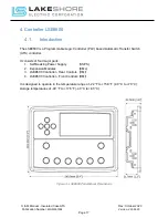
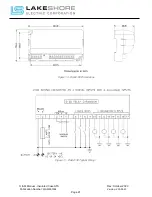
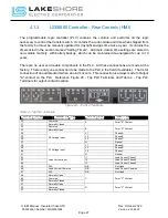
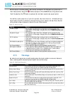
4.1.3.
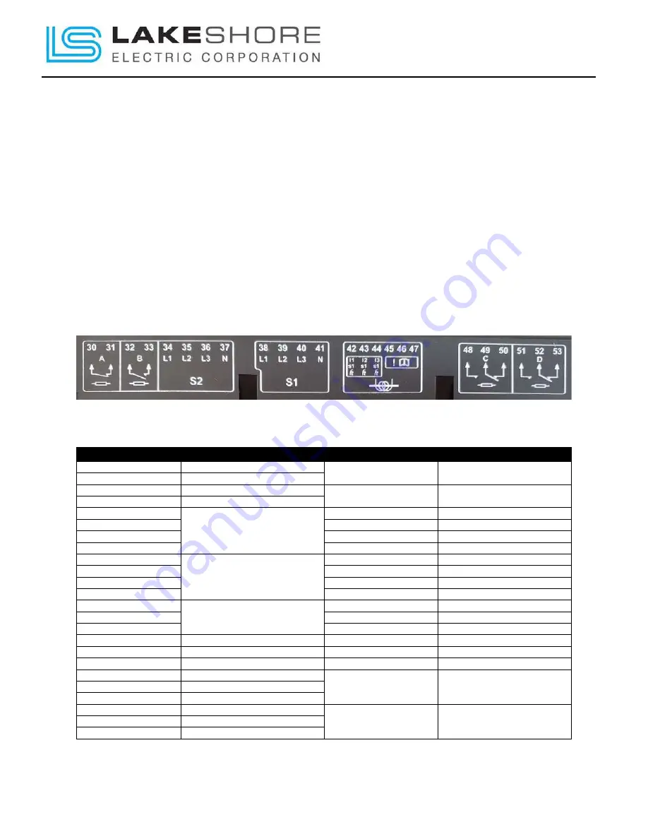
LSE8600 Controller – Rear Controls (HMI)
The programmable logic controller (PLC) contains the controls and performs all the logic
necessary to control the transfer switch. It contains the current date and time when shipped from
the factory but must be manually updated for day light savings time twice a year. It contains the
timers listed in the section marked “Setting Timers”. All timers, date & time settings are stored in
non-volatile memory, with battery backup, which can be maintained de-energized for up to 10
years.
There are no user serviceable components in the PLC. All these connections are made at the
factory. There is only one connection to be made to the PLC in the field (if available). That is for
connection of an audible alarm when an alarm occurs. This connection is always made to Output
"A" contact on the PLC. Reference Figure 20 - Top PLC Terminals and Table 4 - Top PLC
Terminals for output contact location.
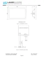
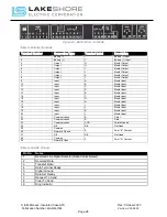
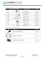
Figure 20 - Top PLC Terminals
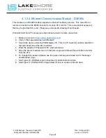
Table 4 - Top PLC Terminals
Terminal Number
Connection Type
Terminal Label
Description
30
Common
A
Form "B" Contact
31
Normally Closed
32
Common
B
Form "A" Contact
33
Normally Open
34
S2 Voltage Input
L1
Phase A
35
L2
Phase B
36
L3
Phase C
37
N
Neutral
38
S1 Voltage Input
L1
Phase A
39
L2
Phase B
40
L3
Phase C
41
N
Neutral
42
Load Current Input
I1
Load Current Phase 1
43
I2
Load Current Phase 2
44
I3
Load Current Phase 3
45
N/A
N/A
Not Used
46
Load Current Common
N/A
Load Current Common
47
N/A
N/A
Not Used
48
Normally Open
C
Form "C" Contact
49
Common
50
Normally Closed
51
Normally Open
D
Form "C" Contact
52
Common
53
Normally Closed


