O & M Manual – Insulated Case ATS Rev: October 2020
Publication Number:
MN0100700E
Version: V10.01.20
Page 11
The preceding sequence of operation describes the operation of a basic dual motor, ATS. Lake
Shore Electric offers a wide variety of accessory equipment to meet customer
specifications(s)/requirements(s). Please refer to the schematic diagram provided with your Lake
Shore ATS for the specific controls provided.
NOTE: For a UTILITY TO UTILITY (Dual Prime Source) application, a preferred source selector
switch is provided on all transfer switches built for Utility-to-Utility applications. The sequence of
operation does not include the "S2 Start Delay" or "Engine Generator Start Delay"
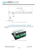
3.
Installation
The LSE8600 controller monitors the voltage source of both S1 and S2 directly to verify that the
sources are within acceptable parameters. The ATS will not operate on a voltage other than that
stamped on the nameplate of the transfer switch, so please verify the equipment received is built
for the system it is being installed within.
3.1.
Mounting and Connecting
The standard Lake Shore transfer switch is designed for operation in a clean, dry, dust-free
location where a minimum of vibration is present.
When used in conjunction with an engine generator set, it is recommended that the transfer switch
be located as close as possible to the generator set, as this will reduce the length of the DC control
wiring (required for automatic operation). This will help with preventing voltage drops and
improper operation. See Table 1 - Control Wire Setup for recommended ATS to Generator
distances.
Table 1 - Control Wire Setup
Control Wire (See Schematic for Terminal #’s)
Max Distance
Wire Gage Size
DC Power
1400 feet
#10 awg
Engine Start Signal
1400 feet
#10 awg
Table 2 – Enclosure NEMA Ratings Available
Lake Shore Electric Enclosure Style Offerings
Ratings
Wall Mount
NEMA 1
Free Standing
NEMA 3R
NEMA 12
NEMA 4
NEMA 4X
Open (Customer Supplied Enclosure)
None (Customer Supplied Enclosure)