24
Settings
NOTE
The flow control device and the by-pass valve are set according to specification and sealed. Any
modifications to these settings lie in the sole responsibility of the customer and must only be carried out
by expert staff.
The adjustment of the flow control device should not be made without the help of proper measuring
equipment, as the switching point must be set in a controlled way. Otherwise the function of the safety
circuit might not be reliable and, as a result, the device to be cooled might get damaged.
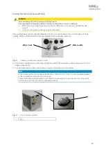
Flow control device
The flow control device contains a closing contact whose OFF threshold is pre-set to a throughput of
4.0 liters per minute. For setting the switching point the switch head must be adjusted. For that
purpose, the screw retained by red locking varnish must be released and the switching head must be
moved while the throughput change is monitored by means of the equipment implemented for that
purpose. After setting the switching point the head fixing screw must be tightened firmly again.
By-pass valve
The by-pass valve is set by the manufacturer to a maximum pressure of 8 bars. If any modification to
this setting should be required, please contact the Laird Thermal Systems service department to
receive briefing.
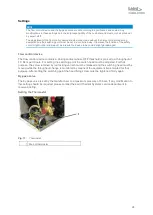
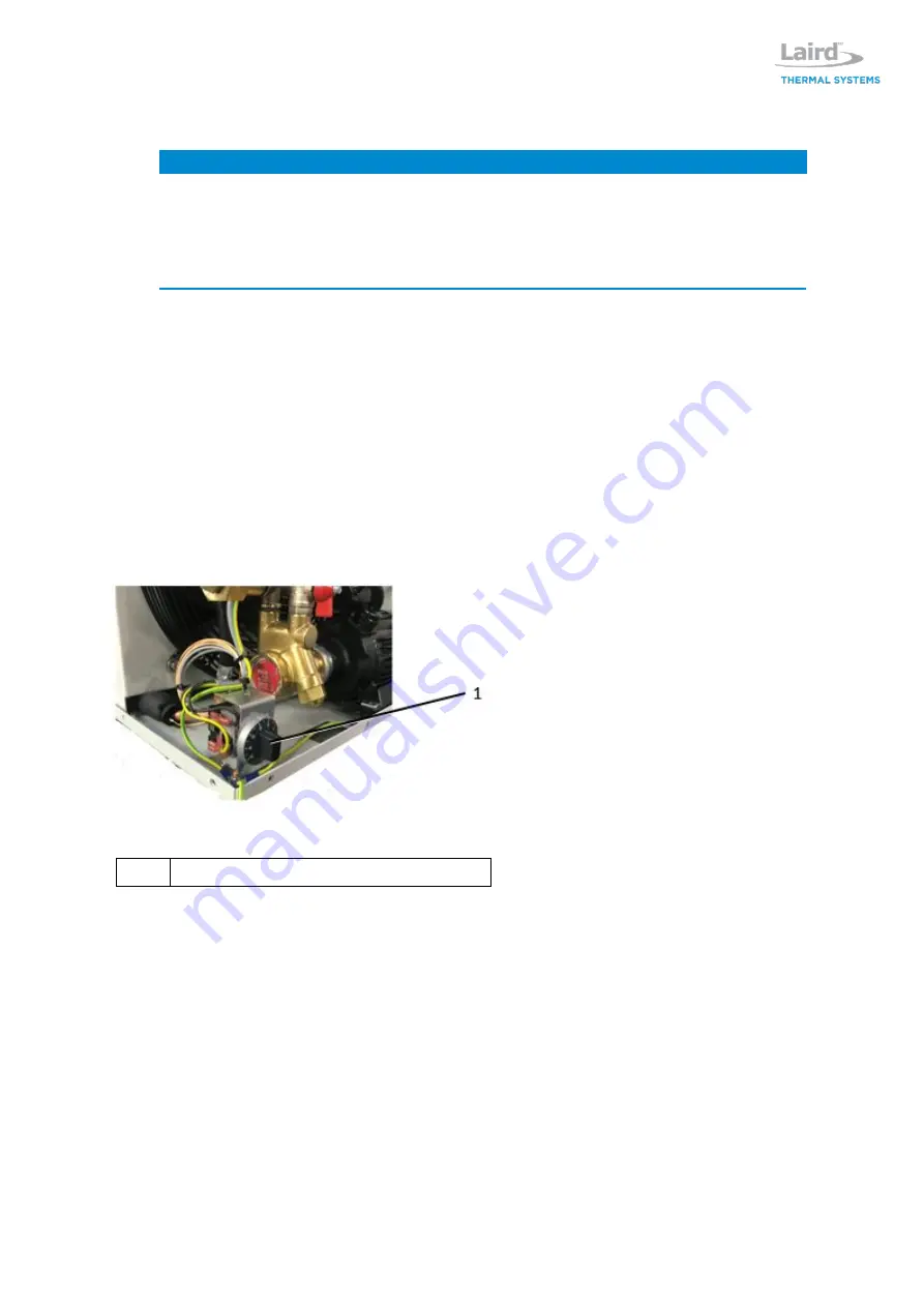
Setting the Thermostat
Fig. 11:
Thermostat
1 Knob of thermostat
Содержание WL3004
Страница 1: ...WL3004 Liquid to Air Cooling System Specification and User Manual Version 1 2 ...
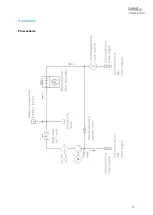
Страница 35: ...35 Addendum Flow scheme ...
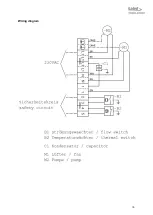
Страница 36: ...36 Wiring diagram ...
Страница 37: ...37 ...

