Sentrius RG191+LTE
User Guide
https://www.lairdconnect.com/wireless-
modules/lorawan-solutions/sentrius-
RG191+LTE-lora-enabled-gateway-wi-fi-ethernet
47
© Copyright 2020 Laird. All Rights Reserved
Americas
: +1-800-492-2320
Europe
: +44-1628-858-940
Hong Kong
: +852 2923 0610
10.4.2
Assembly Steps
The steps explained below cover the power cable assembly process in detail. The ethernet cable assembly is very similar,
however less complex, to work with. In general, place the Ethernet cord through each component and mount to the
enclosure. Tighten the Sealing Nut with a
Torque Force of 8 ~ 10 kgf.cm
. The rest of the guide covers the power cord
assembly.
Note:
To ensure the IP67 rating, the Ethernet cable diameter must be in the range of
4.5 mm
– 6.5 mm. If the cable is too small, there is a potential risk of environment factors potentially
damaging the internal hardware.
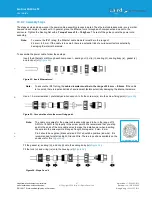
To assemble the power cable, follow these steps:
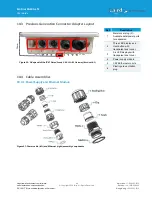
Insert the Ethernet cord through each component
– sealing nut (i), clip (ii), sealing (iii), sealing body (iv), gasket (v),
and lock nut (vi) (
Figure 52: Insert Ethernet cord
Note:
To ensure the IP67 rating, the
cable diameter must be in the range of 5.5 mm
– 8.0 mm
. If the cable
is too small, there is a potential risk of environment factors potentially damaging the internal hardware.
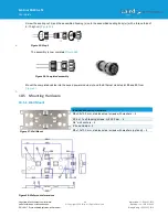
Use a 1.5 mm screwdriver, preferably an allen wrench, to fix the core wire(s) into the screw fixing point (
Figure 53: Core wire fixed into the screw fixing point
Note:
The cable core wires for the power cable assembly need to be in the range of 14
AWG to 18 AWG to fit properly in the screw points. We recommend that you strip
and tin the ends of the core cable wires to make the install easier when inserting
the wire into the screw points. Range of length tinning wire: 5 mm
– 6 mm.
Pin 2 should be negative (black wire) and Pin 1 should be positive (red wire). It is
recommended to install an Earth Ground Wire. There are positions available on the
enclosure for this (
).
Fit the gasket (v), sealing (iii), and clip (ii) onto the sealing body (iv) (
Fit the lock (vi) and o-ring (ix) onto the housing (vii) (
Figure 54: Steps 3 and 4
Содержание 450-00107-K1
Страница 1: ...User Guide Sentrius RG191 LTE Version 1 1 ...

