29
PXl16 Sheartec:II Planer \ Maintenance
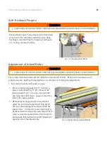
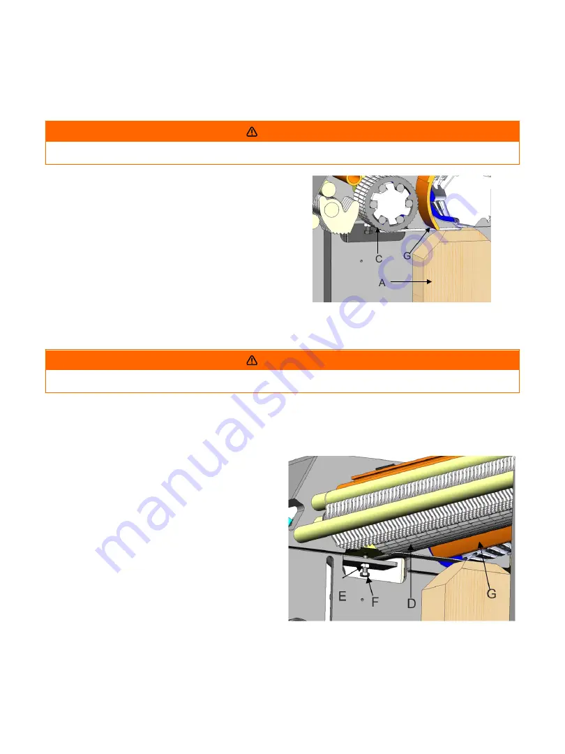
Anti-Kickback Fingers
WARNING
·
TURN PLANER OFF AND DISCONNECT POWER BEFORE PERFORMING ANY MAINTENANCE OR ADJUSTMENTS!
Anti-kickback fingers help prevent stock from being
kicked out of the machine towards the user. Keep
the fingers clean and free from sawdust, pitch gum,
etc., so they operate smoothly.
FIG. 17: FINGER ADJUSTMENT
Adjustment of Infeed Roller
WARNING
·
TURN PLANER OFF AND DISCONNECT POWER BEFORE PERFORMING ANY MAINTENANCE OR ADJUSTMENTS!
The in-feed roller should be set 0.02” below the lowest point of knife. Make sure the knives are set
properly see the “Setting / Changing Knives” section prior to making any adjustments.
1. Disconnect machine from power source.
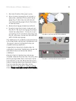
1. Place a hard wood gauge (Fig.17, A) under a
knife in cutterhead (Fig.17, B). Place a 0.02”
feeler gauge (Fig.17, C) on top of wood block
and raise table until feeler gauge contacts the
knife in its lowest position.
2. Remove feeler gauge and place wood block
under the left side of infeed roller (Fig.18, D).
The top of wood gauge should just contact the
infeed roller. If it doesn’t, loosen jam nut (Fig.
18, E) and turn the adjusting screw (Fig.18, F) to
raise, or lower the infeed roller until it contacts
wood gauge then tighten the nut (E). Repeat for
opposite side of the infeed roller.
FIG. 18: INFEED ROLLER ADJUSTMENT
Содержание Sheartec:II PXl16
Страница 1: ...PXl16 Sheartec II Planer Owner s Manual MPLANPX16 0130 3 10 2021...
Страница 24: ...24 PXl16 Sheartec II Planer Setup Assembling FIGURES 10 12 DRO ADJUSTMENT...
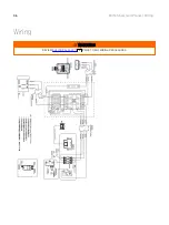
Страница 36: ...36 PXl16 Sheartec II Planer Wiring Wiring WARNING REVIEW ELECTRICAL SAFETY PRIOR TO ANY WIRING PROCEDURES 9...
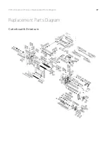
Страница 37: ...37 PXl16 Sheartec II Planer Replacement Parts Diagram Replacement Parts Diagram Cutterhead Drivetrain...
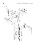
Страница 38: ...38 PXl16 Sheartec II Planer Replacement Parts Diagram Table Lift...
Страница 39: ...39 PXl16 Sheartec II Planer Replacement Parts Diagram Stand Motor...
Страница 47: ...47 PXl16 Sheartec II Planer Warranty...

