


Page
6
of
23
Cha
p
ter:
4
Qu
ick
Sta
rt
Se
ctio
n
6
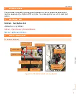
3.5 CHANGING TOOLS
1.
A tool can be inserted or removed two ways
o
Manually - Using the tool release button on the side of the spindle (figure 1)
o
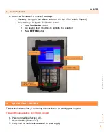
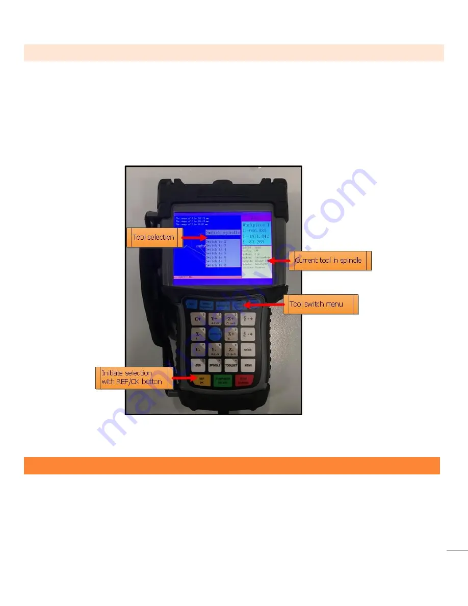
Automatically - Using the Tool Switch button
Press
ToolSwitch
button
Use up and down Y buttons to highlight tool selection
Press
REF/OK
button
4
QUICK START SECTION
This section is a work flow, from turning the machine on, to starting your program.
This walkthrough assumes only TOOL 1 is used.
1.
Power on machine (Section 3.1).
2.
Home machine (Section 3.2).
3.
Verify that the machine is connected to an air supply.


