


Chapter 6: Maintaining the Nano Enclosure
Product Service 1-800-522-7658
33
Calibrate and Operate the Airflow Monitors
Labconco Airflow Monitor/Airflow Switch Operation:
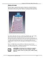
The Guardian Airflow Monitor (LED) consists of a circuit board and an airflow
switch. This switch indicates airflow as safe or low. It does not provide an actual
face velocity, but a small setscrew in the back of the sensor can adjust the airflow
level that it classifies as “good/safe” or “low/alert.”
The circuit board provides power to the sensor and also contains a “safe (green)”
and “alert (red)” airflow LED indicators, as well as a “SILENCE ALARM” button
to quiet the audio alarm. When first powered up, the PCB will light both red and
green LED indicators and sound the alarm to indicate it is working. After 5
seconds, the air monitor will indicate either good or bad airflow based on what the
connected airflow switch detects. For low airflow, the unit will wait for 10 seconds
of bad indications before it sounds both the audio alarm and the red “alert” LED
indicator. If the “SILENCE ALARM” button is pressed, the audio alarm will be
silenced, but the red “alert” LED will remain on. The alarm is silenced indefinitely
unless an airflow change is detected. If safe airflow is later detected for 10 seconds,
the green “safe” LED will be lit and the “alert” (red) LED will be shut off. At any
time the airflow is safe/good, one can press the SILENCE ALARM test button and
the audio alarm and the red LED will turn on as long as this button is held down.
The circuit board has also a two-pin connector for use as an external output with
isolated relay contacts that close when the red/alert LED is lit (low airflow). These
relay contacts are not affected by the “SILENCE ALARM” button.
The circuit board is mounted behind the front panel using standoffs and an
appropriate label is used to highlight the “SILENCE ALARM” button with clear
areas for the red and green LED’s. No holes to allow sound to be broadcast louder
are necessary.
The circuit board can be prepared as a factory special with an additional connector
for the following external inputs, and having the following possible functions:
External Alarm allows an external signal to sound the alarm, such as a sash
open switch, or a “fail” signal from the building airflow system.
Alarm Disable allows an external signal to prevent a “low” airflow alarm from
occurring.
Contact Labconco for ordering information on this special circuit board.
Calibration
1.
Ensure the flow switch and alarm circuit board are installed and
operational.
2.
Allow the enclosure to operate for at least two minutes.
3.
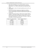
If factory installed, the monitor will alarm at 60±10 fpm with the inflow
velocity set at 90±10 fpm.
4.
To change the factory setting, set the inflow velocity required by your
Safety Officer to the desired alarm condition using the speed control
adjustment procedure outlined in Chapter 6.
Содержание XPert 38872 Series
Страница 17: ...Chapter 3 Getting Started Product Service 1 800 522 7658 13 Figure 3 3 10 NOMINAL ON THE 5 AND 6 10 06 ID...
Страница 59: ...Appendix A Replacement Parts Product Service 1 800 522 7658 55 15 16 10 12 14 2 1 5 6 7 9 3...
Страница 60: ...Appendix A Replacement Parts Product Service 1 800 522 7658 56 17 4 17 17 8 7 10 15...
Страница 63: ...Appendix B Dimensions Product Service 1 800 522 7658 59 Figure B 3 5 and 6 x 35 64 Deep XPert Nano Enclosure...
Страница 64: ...Appendix B Dimensions Product Service 1 800 522 7658 60 Figure B 4 5 and 6 x 29 13 Deep XPert Nano Enclosure...
Страница 65: ...Appendix B Dimensions Product Service 1 800 522 7658 61 Figure B 5 5 and 6 x 35 64 Deep XPert Nano Enclosure...
Страница 66: ...Appendix B Dimensions Product Service 1 800 522 7658 62 Figure B 6 5 and 6 x 29 13 Deep XPert Nano Enclosure...


