background image


66 

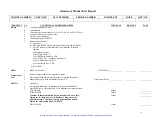
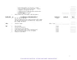
INSP/TESTS No. CONDITIONS 

AND 

REQUIREMENTS  


INST/LCC#   RESULTS   PASS 

partially wetted. Top of heater must be partially unwetted. 
Close door and resume DIAGNOSTICS 


WASH 

PUMP 


Visual 


DETERGENT 

CUP 


Audible 


HEATER                             7.8 - 9.6 Amp 


Ammeter   


Return to TAP – Allow water to fill washer until it turns off. Press 
and hold RUN – Water must turn off before it overflows. 


Visual 


DRAIN / COOL – Allow all water to drain 


Visual 


DRY 

BLOWER 


Audible 


LIQ DETERG PUMP         .1 - .2 Amp  


Ammeter   


LIGHT 


Visual 


FAN 


Audible 


RINSE AID PUMP             .1 - .2 Amp 


Ammeter   


Run Test 

Close Detergent Cup Door 


 2 

Scroll 

through 

Programs 


   Confirm Display Information 


Visual 


Place known amount of water in test dispense bottles 


Select Glass Plus 
Wash 2 Temp 93°C 
Wash 2 Time 10 min 
Steam Yes 
No. Rinses 3 
No. Pure Rinses 1 
Final Rinse Temp 60°C 
Dry Temp 60°C 
Dry Time 20 minutes 
Detergent Dispense 20 ml 
Rinse Aid Dispense 6 ml 
Start Data Acquisition Computer – Identify file with washer serial 
number and date 


    Press RUN    


      Confirm operation of washer, temperatures and times 
          Acceptance Criteria: 


Visual-  
RS232 


              Wash 2 and Final Rinse Temp  +/- 3°C 


              Dry Temp   +/- 8°C once reached 


Artisan Scientific - Quality Instrumentation ... Guaranteed | (888) 88-SOURCE | www.artisan-scientific.com

Содержание 44003 Series

Страница 1: ...uy your excess underutilized and idle equipment along with credit for buybacks and trade ins Custom engineering so your equipment works exactly as you specify Critical and expedited services Leasing R...

Страница 2: ...lassware Washers Model 4540031 Labconco Corporation 8811 Prospect Avenue Kansas City MO 64132 2696 800 821 5525 816 333 8811 FAX 816 363 0130 E MAIL labconco labconco com HOME PAGE www labconco com Gl...

Страница 3: ...A Filter 13 Installing Adjusting the Upper Rack 14 Making Adjustments to the Spindle Rack 15 Installation of the Cool Drain Water Kit 17 Installation of the Liquid Detergent Dispenser 18 Section III T...

Страница 4: ...e 64 Section VI Wiring Schematics 68 115V SteamScrubber and FlaskScrubber 69 230V SteamScrubber and FlaskScrubber 70 208 230V FlaskScrubber Vantage 71 Section VII Parts 72 FLASKSCRUBBER STEAMSCRUBBER...

Страница 5: ...ndles on this rack can be swapped out with different sizes tall short and thin or removed to create a flat rack The SteamScrubber includes both an upper and lower open rack The racks are able to accom...

Страница 6: ...and ordering the washer and accessories that is right for you contact the Sales Support Representative for your geographical region which can be found by calling Labconco or visiting our website For h...

Страница 7: ...m and 6 00 p m Central Standard Time Warranty Labconco provides a warranty on all parts and factory workmanship The warranty includes areas of defective material and workmanship provided such defect r...

Страница 8: ...n to the previous screen before the unit was turned off If the washer was in the middle of a cycle it will continue where it left off however if the wash motor was running and the unit was turned off...

Страница 9: ...de Press and buttons to select the appropriate set point The arrow on the lower right side means that there are additional parameter selections that will be shown on the display if the button is press...

Страница 10: ...eard to open 10 Press the button and the arrow on the display will point to HEATER 11 Press either the or button and the heater will be energized 12 Press the button and the arrow on the display will...

Страница 11: ...oftware sometimes it is necessary to reset the PC Board If you experience a Lock up on the display screen or if your programs aren t being saved follow the directions below to perform a FACTORY RESET...

Страница 12: ...pump will kick on and the water will leave the tank Drying Blower Light Green Left Center The blowers are different between the FlaskScrubber and SteamScrubber These blowers circulate air through the...

Страница 13: ...iddle panel 3 Pull the middle panel forward and remove it 4 Remove the cover over the electrical junction box by removing the two screws disconnecting the wiring connections for the door fan and slidi...

Страница 14: ...ack and side panels of your washer To Remove the Cosmetic paneling of the Washer 1 Turn off electrical power to the Glassware washer 2 Remove all of the screws from the back panel of the washer and re...

Страница 15: ...steel parts In some cases the finish may be slightly dulled by this action If the hot tap water source has a high mineral content film or spots may develop on the washer interior If the procedures li...

Страница 16: ...r screws from the valve plate and separate the valve from the inlet connection 6 Remove the valve filter screen and clean it under running water 7 Replace the screen and reassemble the valve connectio...

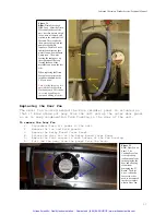
Страница 17: ...ed hole is located below the water distribution channel Maintaining the Air Gap in the Drain If the installation included an air gap recommended it requires periodic cleaning The air gap is not part o...

Страница 18: ...Door Latch move the plate in the direction of the Blue Arrow 4 To loosen the latching action of the Door Latch move the plate in the direction of the Yellow Arrow NOTE If this fails to correct the pro...

Страница 19: ...with soil from glassware that has not been rinsed prior to being placed into the washer or if it becomes coated with minerals from the water supplied to the washer If cleaning the sensor fails to cor...

Страница 20: ...the sensor use Teflon Tape on pipe threading Replacing the HEPA Filter FlaskScrubber Vantage only After an extended period of time dirt and debris may block the air flow through the HEPA filter 1 Ope...

Страница 21: ...ing the Upper Rack The optional upper racks for FlaskScrubbers ship with two 2 each Slide Assemblies and Mounting Bracket Assemblies See Figure below 1 Remove the acorn nuts and lock washers from both...

Страница 22: ...3 Reposition the rack mounting plate to the slide using the other set of holes Replace 2 nuts 4 Repeat the procedure on the opposite slide Making Adjustments to the Spindle Rack Modification of the S...

Страница 23: ...ndle and turn counterclockwise to remove the spindle 2 In the position previously occupied by the spindle thread into place the short spindle you received with the Pipet Insert 3 Push the Pipet Insert...

Страница 24: ...l supplied with the Spindle Rack or a screwdriver into the slot on the top and turning counterclockwise 2 Replace the standard spindle with a small spindle Installation of the Optional Cool Drain Wate...

Страница 25: ...s used To install the Liquid Detergent Dispenser 1 Disconnect power to the washer 2 Remove the back panel Loosen the insulation jacket to provide access to the back of the washer 3 Attach the dispense...

Страница 26: ...the door latch to the right 2 Press the button until the arrow on the left points to LIQ DETERGENT OPT 3 Press the or button to activate this accessory 4 Press RUN to save all settings Using the liqui...

Страница 27: ...ded correctly Tilt these articles when loading so that water drains off Recondensation If clean labware is left in the washer recondensation may occur Open latch after completion of cycle to allow moi...

Страница 28: ...door have surface rust Glassware is contaminated with mineral acids Pre rinse glassware Clean with stainless steel cleaner and soft cloth Washer does not run No power to washer Check fuse or circuit b...

Страница 29: ...ter blocked Check filter in washer and clean as needed Drain valve or pump not operating Check operation Washer will not fill Fill valve clogged Clean fill valve Water supply turned Off Turn on water...

Страница 30: ...ibbon Cable Check Connectors between Ribbon Cable and PC Board Drain Fail Alarm Drain Valve inoperable Listen for click when washer should drain Check for mechanical restriction of actuator arm on top...

Страница 31: ...act Labconco Product Service Water High Alarm Holes in filter screen too small Contact Labconco Product Service Defective hose to fill switch Check for splits Check for loose clamps Defective fill lev...

Страница 32: ...r valves Check voltage to valves Replace valve if it does not operate Restricted flow Check for kinks in water hoses in base of washer to water inlet fitting on side of tank Defective DI water pump Ch...

Страница 33: ...signaled with an audible sound which self cancels after 1 minute HOT GLASS This displays at the end of a cycle if the temperature inside the washer is over 122 F 50 C The alarm cancels when the temper...

Страница 34: ...oint temperature within 135 minutes Operation of the washer continues The alarm cancels when the door is opened TEMP SENSOR This displays if the PC Board during a cycle fails to receive a signal from...

Страница 35: ...the tank to check the water level It should contact the lower half of the Sump Heater Element Fig 26 Water should not completely cover the heater 5 The following indicates your next step o If it fill...

Страница 36: ...t clock wise to raise the level NOTE If you adjust either of the contacts also adjust the other screw the same amount of turns to keep the proper distance between them 4 Repeat Diagnostic check and ad...

Страница 37: ...l the machine stops filling 6 Open the door and check the water level The water should cover the sump heater element but not be overflowing the door IF the water level isn t covering the heater elemen...

Страница 38: ...tic and systems check 1 Open the door latch 2 Push and hold the button 3 While holding the button simultaneously close the latch and hold the button until the machine beeps 4 Scroll down to Tap Fill a...

Страница 39: ...to be free of leaks and the base dried out turn the unit on and verify that the alarm has been cleared and that the unit is ready for service LIQ DETER RINSE AID ALARMS The PC Boards of the new washer...

Страница 40: ...ore undertaking these procedures please do the following preliminary check If you look in User s Instructional Manual pages 15 and 16 there are diagrams picturing how to plumb the drainage lines Make...

Страница 41: ...placement instructions 3 Turn off and On the Drain test and watch the actuation lever on the valve Valve Pump Diagnostic 1 Go to the Diagnostic Menu as described in Section I of this manual 2 In diagn...

Страница 42: ...prime when you restart it That includes low points in the hose between the tank and the drain plumbing connection If both the valve and pump come on verify water is coming out of the drain hose Hose...

Страница 43: ...s from the fill switch mounted on the back of the unit and check resistance between the two terminals on the switch to see if the switch is open or closed If switch closed replace wires and resume cyc...

Страница 44: ...of the washer and measure the actual temperature of the water WATER MAY BE VERY HOT If the measured temperature agrees with the displayed temperature GO TO CHECKING THE FUNCTION OF THE SUMP HEATER If...

Страница 45: ...en the opening screen is displayed Press and hold the button 5 The display should agree with temperature meter 2 C 6 Record Readings a Temperature Probe _____________ Washer Probe ____________ 7 Proce...

Страница 46: ...the wiring and the probe was found to be out of its tolerance in the Checking the Calibration of the Probe Section the probe should be replaced Replacing the Temperature Sensor 1 Separate the connect...

Страница 47: ...these instructions Accessing the Control Module 1 Open the washer s door 2 Remove the mounting screws on the door s backside that secures the grey plastic Control Panel and the screws on the side of t...

Страница 48: ...over the PCB placing the long pins in their spots 12 Secure the Display Panel with the mounting screws 13 Place the Display Module into its housing and secure it with the six mounting screws PC Board...

Страница 49: ...the display 12 Press or to activate the control for the liquid detergent dispense option if this accessory has been installed 13 Press the button and FACTORY RESET will be highlighted on the display 1...

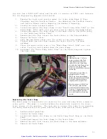
Страница 50: ...ater pressure to fill the tank when set to fill via tap The Tap water valve when fed with proper pressure should allow the tank to fill to the appropriate level within three 3 minutes Removing the Tap...

Страница 51: ...the flange of the base weldment a The two screws holding the valve to the base weldment are countered by nuts on the inner side of the valve These will need to be held secure while removing the screws...

Страница 52: ...secured to the pump place it over the four mounting screws 8 Tighten down the four lock nuts 9 Test the pump in diagnostics Water Level Pressure Switch Hose Replacement Use the following procedures t...

Страница 53: ...Switch 9 Reconnect the connections as shown on the wiring diagram a 5 yellow to 22 b 7BC Black to 21 c 7AB Black to 11 d 6 Orange to 12 10 Test the unit in diagnostics a Fill the unit in tap and check...

Страница 54: ...in diagnostics a Fill the unit in tap and check the water level and for leaks b Drain c Fill the unit with DI Pure if applicable and check the level d Drain 10 Run a Rinse Only cycle to test for any a...

Страница 55: ...Figure 21 Above Left Wash Pump from Right Side The Blue Bracket is the Drain Pump Motor Assembly The Green Circle indicates where the Wash Pump Inlet hose is clamped to the pump The Yellow Circle hig...

Страница 56: ...crews NOTE Also use this procedure for replacing the wash arm assembly found on the Upper Basket and Spindle Racks Replacing the Detergent Cup The Detergent Cup is operated by a wax motor that is sign...

Страница 57: ...creen that covers the sump is designed to keep medium to large particulates glass shards beads boiling rocks etc from getting into the Wash and Drain Pumps These particulates have the potential to che...

Страница 58: ...nnect the wire connectors Figure 25 Left Sump Screen before the Water Distribution Channel has been connected The Red Arrow shows the single screw that holds the sump screen down to the sump below Thi...

Страница 59: ...the unit you are working on Completely drain and disconnect electrical power to the unit before proceeding with any of these instructions Replacing the Blower on a Labconco SteamScrubber The Blower is...

Страница 60: ...ducting that transfers the air to the manifolds The blower is fed air through the HEPA filter found in the side cabinet 1 Pull the unit away from walls cabinets so that you have access to the back an...

Страница 61: ...FAIL ALARM FIRST READ AND GO THROUGH THE DRAIN FAIL ALARM TROUBLESHOOTING CHAPTER The parts listed below do not include every part critical to the drain system however those not listed will be mention...

Страница 62: ...drain pump is responsible for draining the tank and sump after a wash or rinse cycle The pump is located behind the electrical board in the front right corner of the machine The best way to access thi...

Страница 63: ...on at the Drain Pump and tighten the clamp 4 Replace the zip ties removed in the same locations 5 Make sure the Drain Hose is routed properly through the machine See Figures below Figure 30 Left Drain...

Страница 64: ...lamped and zip tied to the outer shell of the tank This loop holds the water used to prime the pump for each drain sequence The Blue Arrows indicate the direction that water flows when the Drain Pump...

Страница 65: ...saved and reinstalled when the new gasket is put into place 2 The replacement rubber gasket will be cut longer than necessary Place one end of the gasket at the far bottom ledge of the washer Fig 1C...

Страница 66: ...he washer and install the new gasket 3 Replace the clips and use RTV Silicon to seat and seal the gasket into place Figure 34 Above Left Baffle Gasket and Clip D The baffle gasket seated in its housin...

Страница 67: ...er Vantage 115 230V SteamScrubber and FlaskScrubber FINAL INSPECTION PROCEDURE FOR STEAMSCRUBBER AND FLASKSCRUBBER Rev Date By Description ECO 2 5 07 LLK Release D533 A 2 12 07 LLK Drawing Provided E1...

Страница 68: ...indow models only 5 Set Liquid Deter Opt NO 6 Set Factory Reset YES D Press RUN Hi Pot 1 1000V for 1 minute Hi Pot Tester Temperature 1 Position thermocouple near temperature probe Test 2 Press and ho...

Страница 69: ...es 1 No Pure Rinses 1 Final Rinse Temp 60 C Final Rinse Temp 60 C Dry Temp 60 C Dry Temp 60 C Dry Time 20 minutes Dry Time 20 minutes Start Data Acquisition Computer Identify file with washer serial n...

Страница 70: ...2 Unit must be Clean and Dry Visual 3 All parts in place in good condition Visual 4 Verify that thermostat on back of tank is installed properly Visual 5 Make sure drain hose is routed over top of was...

Страница 71: ...v Date By Description ECO 5 8 07 LLK Release E318 A 7 16 07 LLK Added Overfill Test E419 B 8 2 07 LLK Clarified Verbiage No Change to Tests E459 C 12 21 07 DKT Dry temp tol Was 5 deg E665 Artisan Scie...

Страница 72: ...actuate function 1 Set Temp Units C 2 Set DI Pump to Enable YES 3 Set Light ON 4 Set Factory Reset YES D Press RUN Hi Pot 1 1000V for 1 minute Hi Pot Tester ____________ Temperature 1 Position thermo...

Страница 73: ...mp Ammeter Run Test 1 Close Detergent Cup Door 2 Scroll through Programs Confirm Display Information Visual 3 Place known amount of water in test dispense bottles 4 Select Glass Plus Wash 2 Temp 93 C...

Страница 74: ...rfaces Visual After wash pump starts place a wet towel across the overflow contacts Wash pump should stop and the washer should drain Display should show ALARM OVERFLOW Hi Pot 1 1000V for 1 minute Hi...

Страница 75: ...to the extensive nature of electrical troubleshooting there will not be any detailed instructions on how to perform step by step electrical testing of systems The wiring schematics can aid you through...

Страница 76: ...Labconco Glassware Washer Service Technical Manual 69 115 Volt FlaskScrubber and SteamScrubber Artisan Scientific Quality Instrumentation Guaranteed 888 88 SOURCE www artisan scientific com...

Страница 77: ...Labconco Glassware Washer Service Technical Manual 70 230 Volt FlaskScrubber SteamScrubber Artisan Scientific Quality Instrumentation Guaranteed 888 88 SOURCE www artisan scientific com...

Страница 78: ...Labconco Glassware Washer Service Technical Manual 71 208 230 Volt FlaskScrubber Vantage Artisan Scientific Quality Instrumentation Guaranteed 888 88 SOURCE www artisan scientific com...

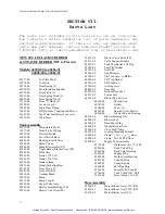
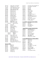
Страница 79: ...Clip LH 45181 00 Door Clip RH 45832 00 Vacuum Break 45820 00 Sump 45831 00 Sump Coupler 45830 00 Supply Tube Assy 45829 00 Blower Hose Bushing FS 45822 00 Blower Valve Seat FS 45821 00 Blower Valve B...

Страница 80: ...ical Enclosure Cover 45861 01 Water Deflector Baffle Assy 45861 03 PCBoard Enclosure Gasket 45861 00 Control Panel 45854 00 PC Board Assy 45854 03 PC Board Assy 45162 00 Soap Dispenser Mounting Bracke...

Страница 81: ...230V 50777 03 Solenoid Valve SubAssy 45875 00 Liquid Detergent Dispense Kit 45914 00 Wire Assembly 45878 00 Cap Assembly 45875 02 Pump Assembly 45961 00 Mobile Conversion Kit 115V 45965 00 Hose Assemb...

Страница 82: ...w 14 18983 06 Screw 12 44680 00 Plug 2 19302 00 Nut 2 46038 00 Conversion Kit 1 Top Panel is required when adding any combination of the back or side paneling For a complete conversion of an Under cou...

Страница 83: ...uipment Have surplus equipment taking up shelf space We ll give it a new home Learn more Visit us at artisantg com for more info on price quotes drivers technical specifications manuals and documentat...

Отзывы: