


Pennant Pool Heater
Page 21
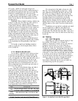
Figure 8. Typical Control Panel.
8.2 Delayed Ignition - Possible Causes
A defective burner can cause a delayed ignition.
If the gas supply pressure is proper and the gas valves
are functioning properly, then burners should be
inspected. There should be no distortion or
perforations in the burners outside of the active burner
port area. Replace if indicated.
8.3 Short Cycling
Because of the large mass of pool systems, short
cycling should not exist. If it does, it will be caused by
insufficient flow in the pool loop. Check that there is
no blockage in the pool loop such as a plugged or
partially plugged pool filter.
8.4 High Gas Consumption
Appliances operating with an improper air/fuel
ratio are very inefficient and consequently, have very
high gas consumption. Because efficiency is high
when the CO
2
is high (or O
2
is low), appliances
operating with low CO
2
or high O
2
(especially LP
appliances) consume more gas. Adjust the CO
2
or O
2
for optimum efficiency. If no combustion analyzing
equipment (CO
2
or O
2
) is available then a proper
adjustment of the air/fuel ratio (CO
2
or O
2
) cannot be
accomplished. However, by briefly sniffing the flue
gases it is possible to determine if the CO
2
or O
2
is
within the proper range. No significant flue gas odor
should be detected when combustion is proper. A
strong piercing smell indicates poor combustion and
generally a lean mixture - low CO
2
or high O
2
. The
CO
2
should be 8% (natural gas, 9.2% LP) at high fire.
To check the CO
2
, first verify that the supply gas
pressure is within 5" to 13" w.c. (1.2 to 3.2 kPa) With
the Pennant running with both stages firing, set the air
box pressure to 1.5" w.c. (0.37 kPa) (as a starting
point), by adjusting the air shutter(s) at the bottom of
the fan(s). Check the CO
2
, and adjust the air shutters if
further adjustment to the CO
2
is needed. Models 1250,
1500, 1750 and 2000 have two blowers and two air
chambers (boxes). The pressure of each air box must
be equal when the final adjustment is made.
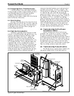
8.5 Troubleshooting the Pool Heater
Temperature Control
With a Voltmeter, test for 24 VAC between
terminals 1 & 2 on the 10 pin connector. Check that
the sensor temperature is lower than the setpoint
temperature by at least the differential setting. If this is
true, check that there is 24 VAC at the yellow wire on
the 4 pin connector. If there is not 24 VAC, check that
the high limit is not open. If there is 24 VAC at the
yellow wire on the 4 pin connector and not at the light
blue wire on that connector, replace the control.
8.6 Troubleshooting Pennant Controls
The Pennant series consists of three models with
one ignition module (500, 750 & 1000) and four
Содержание Pennant PNCP 1000
Страница 28: ...LAARS Heating Systems Page 28 Figure 9 Sheet Metal Components...
Страница 29: ...Pennant Pool Heater Page 29 Figure 10 Internal Components...
Страница 30: ...LAARS Heating Systems Page 30 Figure 11 Heat Exchanger Components A See pump chart below for pump numbers...
Страница 31: ...Pennant Pool Heater Page 31 Figure 12 Pennant 500 1000 Ladder Diagram SECTION 10 Wiring Diagrams...
Страница 32: ...LAARS Heating Systems Page 32 Figure 13 Pennant 1250 2000 Ladder Diagram...
Страница 33: ...Pennant Pool Heater Page 33 Figure 14 Pennant 500 1000 Wiring Schematic...
Страница 34: ...LAARS Heating Systems Page 34 Figure 15 Pennant 1250 2000 Wiring Schematic...
Страница 35: ...Pennant Pool Heater Page 35 Figure 16 Field Wiring PNCP 500 1000...


