


Pennant Pool Heater
Page 15
normally-open contact(s) of the airflow pressure
switch(es). This allows the ignition module to proceed
with the ignition sequence.
The blocked flue pressure switch senses the
pressure difference between the exhaust plenum and
the blower inlet plenum. It will interrupt the airflow
sensing circuit if this pressure exceeds a maximum
value. If airflow is not proven, the ignition module
will either attempt ignition again (up to three times) or
will lockout (if the optional lockout ignition module is
used).
The ignition module checks that the ignitor
current has reached a minimum value and energizes
the gas valves at the end of the ignitor-heating period.
The green indicators on the front panel will light,
indicating that the gas valves are open.
After a 4-second trial for ignition, the ignitor
switches off, and unless the flame sensor detects a
flame, the gas valves will close and the ignition
module will either attempt ignition again (up to three
times) or will lockout (if the optional lockout ignition
module is used).
Note: at this point, if gas pressure is
below the required 5" w.c. minimum, the pool heater
will lock out.
If flame is sensed, the burner will continue to fire
as long as there is a call for heat. Pennant 1250, 1500,
1750 and 2000 models start at part load. When the gas
valves controlled by the first ignition module are
energized, the second ignition module is energized and
enters the same ignition sequence just described. If
there is a subsequent loss of flame signal, the burner
will attempt re-ignition up to three times (only once if
optional lockout ignition module is used.) Loss of
flame signal from the first ignition module will cause
shutdown of the heater.
When the call for heat is satisfied, the gas valves
close and the blower(s) continues to run for 30
seconds. The pump will continue to run for the length
of time selected at startup by the adjustment of the
pump time delay (Pd).
If a call for heat is prevented from being satisfied
either by a safety interlock or due to an ignition
lockout, the red “Service” indicator on the front panel
will light. To reset the standard ignition module,
toggle the Pennant power switch off, and then on
again. (To reset the optional single try lockout ignition
module, the reset button on the module must be
pressed. Interrupting power to this module will not
reset the lockout.)
The Pennant 1250, 1500, 1750 and 2000 models
have two ignition modules that control different
burners.
6.2 Filling the Heater System
1.
Ensure the system is fully connected, filled with
water and all valves are open.
2.
Start up heater according to the procedure in this
manual. Operate the entire system for one (1) hour.
3.
After placing the unit in operation, the ignition
system safety shutoff device must be tested.
First, shut off the manual gas valve, and call the
unit for heat. After the pre-purge and ignitor
heat-up time, the main gas terminals will be
energized, attempting to light, for four (4)
seconds, and then will de-energize. The unit will
go into lockout mode. Second, turn the power off
and then on again, push the reset button (optional
Ignition Module only), open the manual gas
valve and allow the unit to light. While the unit
is operating, close the manual gas valve and
ensure that power to the main gas valve no
longer exists.
4.
Check the entire system for leaks.
Caution
Protect the heater from low pH water if an “acid
start up” or similar technique is used. Corrosion of
the heater and heat exchanger due to low pH water
is not covered under the limited warranty. The water
must be neutralized to normal pH levels before
filling the heater and starting up the system.
Important:
The installer is responsible for identifying
to the owner/operator the location of all emergency
shutoff devices.
WARNING
Do not use this appliance if any part has been
under water. Immediately call a qualified service
technician to inspect the appliance and to replace
any part of the control system and any gas control
that may have been under water.
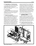
6.3 Operating the Burner and Set Up
6.3.1 Set Up for 0 to 2500 Feet Altitude
The setup must be checked before the unit is put
in operation. Problems such as failure to start, rough
ignition, strong exhaust odors, etc. can be due to
improper setup. Damage to the heater resulting from
improper setup is not covered by the limited warranty.
1.
Using this manual, make sure the installation is
complete and fully in compliance with the
instructions.
2.
Determine that the appliance and system are
filled with water and all air has been bled from
both. Open all valves.
3.
Observe all warnings on the Operating
Instructions label and turn on gas and electrical
power to appliance.
4.
Switch on the appliance power switch located on
the right side of the unit.
5.
The Pennant will enter the start sequence, as long
as the unit is being called for heat. The blower
and pump come on for pre-purge, then the ignitor
warm-up sequence starts and after the ignitor
Содержание Pennant PNCP 1000
Страница 28: ...LAARS Heating Systems Page 28 Figure 9 Sheet Metal Components...
Страница 29: ...Pennant Pool Heater Page 29 Figure 10 Internal Components...
Страница 30: ...LAARS Heating Systems Page 30 Figure 11 Heat Exchanger Components A See pump chart below for pump numbers...
Страница 31: ...Pennant Pool Heater Page 31 Figure 12 Pennant 500 1000 Ladder Diagram SECTION 10 Wiring Diagrams...
Страница 32: ...LAARS Heating Systems Page 32 Figure 13 Pennant 1250 2000 Ladder Diagram...
Страница 33: ...Pennant Pool Heater Page 33 Figure 14 Pennant 500 1000 Wiring Schematic...
Страница 34: ...LAARS Heating Systems Page 34 Figure 15 Pennant 1250 2000 Wiring Schematic...
Страница 35: ...Pennant Pool Heater Page 35 Figure 16 Field Wiring PNCP 500 1000...


