


Page 4
LAARS HEATING SYSTEMS
B
54
1372
C
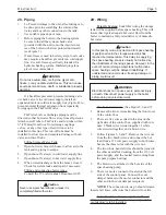
Vent Damper*
Tank
Relief Valve
Tank
Aquastat
Drain
Valve
24
610
A
CL
Hot
Water
Tank
Outlet
Inlet
28
711
FRONT VIEW
SIDE VIEW
24
1
/
2
622
(Sizes 50 & 25)
25
635
(Size 75 & 100)
7
178
Mounted
Pump
System
Check Valve
Check Valve
Mini-Therm
Boiler
(50-125)
24
610
31
787
Boiler
Approx.
MC
A
B
C
In/Out
Gas
Inlet/Outlet
Weight
Size
inches
mm
inches
mm
inches
mm
NPT
NPT
NPT
lbs.
kgs
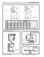
50
58¾
1492
12½
318
4
102
1¼
½
¾
258
117
75
58¾
1492
12½
318
5
127
1¼
½
¾
274
124
100
59¾
1518
14¼
362
5
127
1¼
½
¾
280
127
125
59¾
1518
14¼
362
6
152
1¼
½
¾
286
130
Domestic
Figure 1. Dimensional Information.
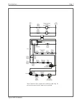
Figure 2. Closet Installation.
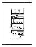
7
178
Figure 4. Typical Expansion Tank Installation.
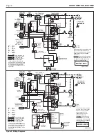
Figure 3. Piping Schematic.
Top Clearance
28
711
2
51
24
610
23
584
4
102
6
152
Dimensions
shown in inches
mm.
Cold
Water
Supply
Hot
Water
Supply
Minimum clearances from
combustible surfaces:
in.
mm
left side
2
51
right side
0
0
rear
6
152
front
4
102
top
23
584
Service clearances:
allow 4
102 on each side
for piping access.
Space Heating -
Refer to Document 1025
Dimensions shown
in inches
mm.
24
610
*Vent damper is optional on some Canadian units.


