background image

INSTRUCTION/OPERATING AND TROUBLESHOOTING MANUAL FOR MODEL EC 

Page 4 of 11 

INSTALLATION AND OPERATING INSTRUCTIONS 


The  EC  Battery  Charger  is  designed  to  operate  on  a  specific  number  of  battery  cells.    The 
nameplate  indicates  the  type  and  the  number  of  battery  cells  required.    Once  properly  installed, 
the charger will maintain the battery in a fully charged condition.  Install the charger so that the 
flow  of  air  through  the  ventilators  is  not  obstructed.    Dress  field  wiring  circuits  at  least  1/4  inch 
away  from  input/output  circuits.    When  hooking  up  the  DC  cables  to  the  battery  be  certain  the 
positive  terminal  of  the  charger  is  connected  to  the  positive  battery  terminal  and  the  negative 
terminal is connected to the negative of the battery.  Check the AC input voltage with voltage on 
nameplate.  If unit does not start re-set AC breaker. 
 
After  the  charger  has  been  installed,  check battery  specifications.    When  the  battery  is  in  a  fully 
charged condition, the float voltage should average 2.17 +.05 volts per cell for lead acid cells, 1.43 
+.01 volts per cell for nickel-cadmium cell.  The equalize voltage should average 2.32 +.05 volts 
per cell lead acid cell, 1.55 +.02 volts per cell equalize nickel-cadmium cell. 
 
The charger is factory tested and preset so that no field adjustments are necessary.   
 
In  normal  operation,  the  EC  Charger  maintains  a  constant  battery  voltage.    If  the  battery  is 
discharged, the charge will recharge the battery on a taper curve from its current limiting capacity 
to full charge.  No permanent loads should be connected to the battery. 
 
The Float/Equalize Switch is used to raise the charger output voltage to 2.32 +.05 volts per cell for 
lead acid cells or 1.55 +.02 volts per cell for nickel-cadmium cells, so that the battery can be given 
an equalizing charge.  To give an equalizing charge, it is only necessary to throw the switch to the 
equalize  position  and  leave  it  there  for  24  hours.    The  charger  will  hold  the  cell  voltage  at  the 
equalizing voltage while the switch is in equalize position and will drop back to float voltage when 
the switch is put back into the normal or float position. 
 
LED’s indicate the equalize or float mode. 
 
The  inherent  design  of  the  ferroresonant  transformer  compensation  for  line  voltage  variations  of  
+ 10%. 
 
The DC output current is limited to provide for complete protection.  The current limiting feature 
allows for the unit to carry overloads and limits the output to a maximum of less than 150% of the 
rated output. 
 
 
NOTE:  This unit is 

not

 recommended for use on sealed valve regulated batteries. 

Содержание EC

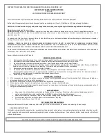
Страница 1: ...FOR MODEL EC Page 1 of 11 EC Engine Start Battery Charger INSTRUCTION MANUAL ECN DATE CPN106604 18985 4 11 16816 11 05 106 BRADROCK DRIVE DES PLAINES IL 60018 847 299 1188 FAX 847 299 3061 ISSUE DATE...

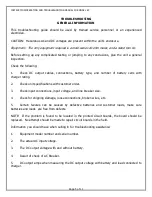
Страница 2: ...the eye with running cold water for at least ten 10 minutes and get medical attention immediately 5 Never smoke or allow a spark or flame in vicinity of a battery 6 Be extra cautious DO NOT drop meta...

Страница 3: ...Mfg may void warranty service for any physical damages reported for repair HANDLING WARNING Equipment can be very heavy and top heavy Use adequate manpower or equipment for handling Until the equipmen...

Страница 4: ...r cell equalize nickel cadmium cell The charger is factory tested and preset so that no field adjustments are necessary In normal operation the EC Charger maintains a constant battery voltage If the b...

Страница 5: ...rating 2 Check unit specifications with customer order 3 Check input connections input voltage and line breaker size 4 Check for shipping damage loose connections broken wires etc 5 Certain failures c...

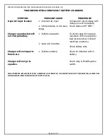
Страница 6: ...operates but will not charge battery 1 Defective capacitor 2 Open cell in battery To check capacitor measure resistance with one capacitor lead disconnected it should read high resistance Check batter...

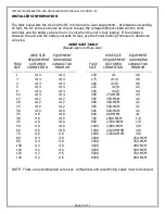
Страница 7: ...MENT REQUIREMENT GROUNDING FUSE CUSTOMER CONDUCTOR SIZE CONNECTION MINIMUM 1 14 14 3 14 14 4 14 14 5 14 14 6 14 14 10 14 14 15 12 12 20 12 12 25 10 12 30 10 10 35 8 10 40 8 10 45 8 10 50 8 10 60 6 10...

Страница 8: ...2000 2000000 Denotes all sizes larger than 0000 are expressed in MCM TABLE OF CONVENTIONS CMA Cross section of wire in circular MIL area A Ultimate drain in amperes LF Conductor loop feet MAX AMP Maxi...

Страница 9: ...4 Check front panel meters and alarms for accuracy 4th Year REPEAT ABOVE WITH THE ADDITION OF 1 Check relay contacts for pitting or corrosion 2 Check capacitors for leakage 7th Year REPEAT ALL WITH T...

Страница 10: ...by purchaser 2 If the purchaser elects not to return the equipment to the factory and wishes a factory service representative to make adjustments and or repairs at the equipment location La Marche s...

Страница 11: ...sting performed by factory personnel Should it be necessary to return a piece of equipment or parts to the factory the customer or sales representative must obtain authorization from the factory If up...

Отзывы: