


8
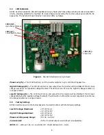
LED3 (HV)
–
High Voltage Shutdown
LED2 (LV)
–
Low Voltage Shutdown
LED1 (PL)
–
Phase Lock
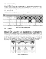
3.4
LED Indicators
All A31 inverters include the S2A-167S oscillator/line sync board which has voltage sensing circuitry and oscillator
circuits, providing protection for low/high DC input voltages and assuring the inverter output syncs with the AC
bypass line. The S2A-167S board includes 3 red status LEDs, as follows:
Phase Lock (PL)
–
This PL LED will turn on if the inverter output is in sync with the AC bypass line.
High DC Voltage (HV)
–
This HV LED will turn on and output from the inverter will be inhibited if the DC input
voltage rises above the specified voltage threshold. The LED will turn off once the high DC voltage condition is
no longer present.
Low DC Voltage (LV)
–
The LV LED will turn on and output from the inverter will be inhibited if the DC input
voltage falls below the specified voltage threshold. The LED will turn off and the inverter output will once the low
DC voltage condition is no longer present.
3.5
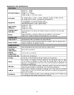
Factory Settings
All A31 inverters are set at the factory based on the model number with the following settings:
Low DC Voltage Shutdown:
1.73 V/C for LA
1.10 V/C for NC
High DC Voltage Shutdown:
2.45 V/C for LA
1.60 V/C for NC
Phase Lock Frequency Range:
57.5 Hz
–
62.5 Hz
Current Limit:
150% of nominal output current (fixed; not adjustable)
NOTE:
V/C
–
Volts per Cell, LA
–
Lead Acid, NC
–
Nickel Cadmium, Hz
–
Hertz
Figure 6
–
S2A-167S Oscillator/Line Sync Board


