41
SOLUTION:
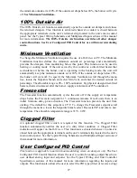
If fan is not running
1.
Is the fan status relay’s normally open contact, closed?
a.
Yes. Replace relay.
b.
No. Continue.
2.
Is there approximately 5VDC at both controller terminals used for the fan
status?
a.
Yes. There is a short in the wiring between these terminals. Determine
cause and rectify.
b.
No. Replace controller.
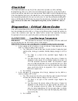
ALARM CODE:
Unit on/Fan off
PROBLEM:
The controller has activated the unit enable output to start the fan,
but the fan status input, is not receiving a signal that the fan is running. This alarm will
automatically clear about 60 seconds after the alarm is corrected. Turning the unit off and
then on will clear this alarm at any time.
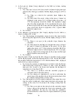
SOLUTION:
If fan/motor is running
1.
Is the
BACview
remote indicating an alarm?
a.
Yes. Check previous alarms and continue.
b.
No. Continue.
2.
Is the motor starter’s normally open auxiliary contact, closed?
a.
No. Replace contact.
b.
Yes. Continue.
3.
Are the high and low velocity airflow switch contacts, closed?
a.
No. Are the belts on and is the fan motor.
1)
Yes. Contact factory. Do not adjust the switches setpoints.
2)
No. Determine cause and rectify.
b.
Yes. Continue.
4.
Is the fan status relay energized?
a.
No. There is an open or break in the wiring. Determine cause and
rectify.
b.
Yes. Continue.
5.
Is the fan status relay’s normally open auxiliary contact, closed?
a.
No. Replace relay.
b.
Yes. Continue.
6.
Is there continuity at the controller between the fan status terminals?
a.
No. There is an open in the wiring between these terminals. Determine
cause and rectify.
b.
Yes. Replace controller.
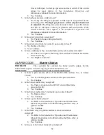
SOLUTION:
If fan/motor is not running
1.
Is the
BACview
remote indicating an alarm?
a.
Yes. Check previous alarms and continue.
b.
No. Continue.
2.
Is controller output LED for the unit enable output lit?
a.
No. There is a problem with the controller. Replace controller.
b.
Yes. Continue.
3.
Is the unit enable relay energized?
a.
No. There is an open in the wiring between these terminals. Determine
cause and rectify.
b.
Yes. Continue.
4.
Is the unit enable relay’s normally open contact, closed?
Содержание AireLogic
Страница 1: ...1 AireLogic Digital Control System User Manual Rev 04 11 13...
Страница 53: ...53 Appendix I 10K Thermistor Output Curve...
Страница 54: ...54 Appendix II Airflow Station Layout...
Страница 59: ...59 Typical Wiring Schematic RECIRCULATING WDF MODEL DIAGRAM...
Страница 60: ...60 NON RECIRCULATING WDF MODEL DIAGRAM...

