background image

4

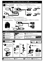
For more information, refer to radio system instruction manual.

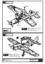
BASIC CONNECTION FOR ELECTRIC POWERED AIRPLANE AND ADJUSTMENT OF SERVOS

Battery

Battery

Motor

Receiver

Receiver

Aileron Servo

Aileron

Elevator Servo

Elevator

Switch

Switch

Switch

Speed Controller

Speed Controller

Basic connection for EP Airplane.

Always set the servos at their neutral position before installing the servos.

Establishing servo’s neutral position.

The servo's reach their neutral position automatically when connected 

according to the 

drawing below 

    and the transmitter/receiver switches are turned ON.

 Explanation of symbols used in this instruction manual.

Drill holes with the specified diameter.

2mm

Must be purchased separately!

Apply epoxy glue.

Assemble in the specified order.

Pay close attention here!

Cut off shaded portion.

Drill holes with the 
specified diameter.

Must be purchased separately!

2mm

Assemble in the specified order.

Warning!

Do not overlook this symbol!

Assemble left and right sides the same way.

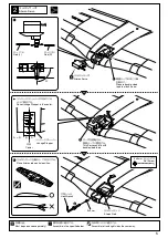
1

Aileron Servo

1

E1.5
           E-ring

2

2mm   
           Washer

2mm

approx. 7mm

E-ring

90°

Aileron Servo

Check neutral position 
before install.

2mm

2

3

4

1

Supplied with 
the servo.

Supplied with the servo.

Attach servo horns 
so they are 90° to 
the linkage rods.

Neutral Condition

Pay close attention here!

電動プレーンの基本とサーボのニュートラル調整

電動プレーンの基本接続図。

サーボを取り付ける前に、
必ずサーボのニュートラルを出しておく必要があります。

●プロポの取扱いは、プロポに付属の説明書を参考にしてください。

■バッテリー

■バッテリー

■モーター

■受信機

■受信機

■エルロンサーボ 

エルロン

■エレベーターサーボ 

エレベーター

■スイッチ

■スイッチ

■スイッチ

■アンプ

■アンプ

サーボのニュートラルの出し方

●図のように接続した状態で送受信機のスイッチをONにすると、自動的にサーボのニュートラルが出ます。

説明書に使われているマーク

2mm

の穴をあける(例)。

別購入品。

エポキシ接着剤で接着する。

番号の順に組立てる。

注意して組立てる所。


をカットする。

2mm

の穴をあける(例)。

別購入品。

番号の順に組立てる。

重要な注意事項があるマークです。
必ずお読みください。

左右同じように組立てる。

エルロンサーボ

E

リング

ワッシャー

7mm

Eリング

エルロンサーボ

サーボホーンを取り付け
る前に、必ずサーボのニ
ュートラルを出しておく。

サーボ付属

サーボ付属

サーボホーンを90°に
なるように取り付ける。

チ・チ・チ・・

注意して組立てる所。

Содержание 10231

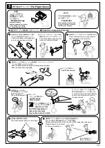
Страница 1: ...this instruction manual ready at hand for quick reference even after completing the assembly The product you have purchased is powered by a rechargeable battery The battery is recyclable At the end o...

Страница 2: ...dvice on pre flight adjustments and assembly from experienced fliers Remember that flying a badly assembled or badly adjusted aircraft is very dangerous In the beginning novice fliers should always be...

Страница 3: ...rol systems This model requires a minimum 4 channel radio control system with 2 micro servos and 1 speed control amp electronic speed controller for aircraft RADIO PREPARATION 1 2 The batteries should...

Страница 4: ...er receiver switches are turned ON Explanation of symbols used in this instruction manual Drill holes with the specified diameter 2mm Must be purchased separately Apply epoxy glue Assemble in the spec...

Страница 5: ...sided tape Place Aileron rod neutral position Place Linkage Stopper in the center Prepare double sided tape to attach Servo Linkage Stopper Center 1 3 x 3mm Set Screw 3x3mm 3 Aileron Servo Must be pur...

Страница 6: ...ill 1 5mm holes for servo position Apply epoxy glue 1 2 3 3 4 Assemble in the specified order Elevator Servo Elevator Servo Check neutral position before install 2mm 2 3 4 1 Supplied with the servo Su...

Страница 7: ...ape Speed Controller Speed Controller Fix with double sided tape Receiver Receiver Refer to radio system instruction manual and connect the leads Feed Receiver antenna through hole Double sided tape F...

Страница 8: ...o Make certain gap between battery and fuselage Velcro Apply Velcro 1 2 2 3 4 Assemble in the specified order 9 Main Landing Gear Front 1 2 Connector Lead 8 4V 600mAh Ni MH Battery Must be purchased s...

Страница 9: ...ing securely to fuselage Loss of wing will result in no control and crashes Warning Fix wing securely to fuselage Loss of wing will result in no control and crashes Extension Lead Do not overlook this...

Страница 10: ...re confirming the correct C of G position If the C of G is incorrect you may lose control of your airplane and crash 13 C of G Position Warning Do not overlook this symbol Warning Pay close attention...

Страница 11: ...Trim accordingly 10mm Do not overlook this symbol Warning 14 Check radio system Replacing the Propeller Throttle Stick Aileron Elevator Up Up Up 10mm 10mm 10mm 10mm 10mm Down Down Down Warning Discon...

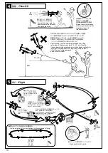
Страница 12: ...ly Flight Conditions Do NOT operate model near these areas First flight should be in light wind speeds up to 2 3m Do NOT use near houses or buildings children s play areas road traffic railways airpor...

Страница 13: ...ays check that no one is using the same frequency band in the same area Make sure power switch on the plane is OFF before connecting battery Make sure no one is near the propeller Do NOT touch switch...

Страница 14: ...le If plane doesn t climb accordingly adjust with elevator control After reaching an altitude of about 40m beginning circling the plane If battery is not charged properly plane will not ascend Wind Fl...

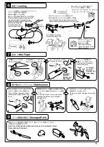
Страница 15: ...cool down before recharging Caution hot after flight Caution hot after flight Maintenance Damaged Parts When not flying disconnect battery connector and remove battery from plane For next flight check...

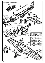
Страница 16: ...3 22 25 24 25 9 5 2 3 11 18 19 12 13 14 17 16 15 6 1 2 3 Screw 16T 64T 3 x 4mm TP Screw TP Screw TP Screw 3 x 16mm TP Screw Washer 3 x 16mm Nut 3mm Nut 3mm TP Screw 2 6 x 10mm Washer 2mm Washer 2mm 2...

Страница 17: ...8 3x20mm 5 3x12mm 5 pieces each Fluorescent Velcro Green Double Sided Sponge Tape 1mm Thick 4 4 pieces 5 5 pieces 20 x 1 1 2 3 x 2 24 25 x 2 22 23 x 1 1 2 5 3 x 1 7 9 x 1 6 x 1 17 x 1 10 x 1 735 12600...

Страница 18: ...lug the battery Cautions for Safety Do not allow people watching to get too close to a rotating propeller Don t use defective propellers and deformed spinners Batteries and chargers become hot Keep aw...

Отзывы: