2
Connections and LEDs
Connections
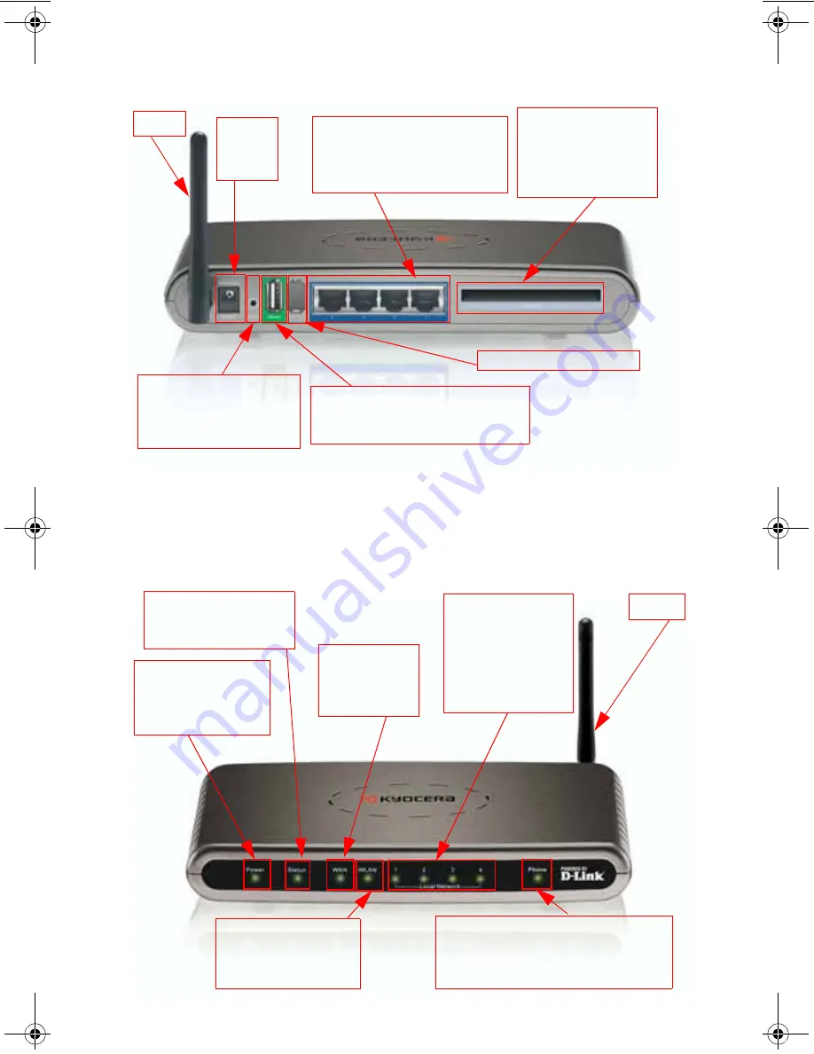
The following figures show the various connectors and status LED indicators on the Kyocera KR1 Mobile Router.
Figure 1: Connections– Kyocera KR1 Mobile Router (Back View)
Note:
The Kyocera KR1 Mobile Router contains two ports: a “Phone-In” USB Port, and a second internal
diagnostic port. Please use only the “Phone In” USB Port for your 1xEV-DO connections.
The second
port is not for customer use. Please do not attempt to use this port
.
LEDs
Figure 2: LEDs– Kyocera KR1 Mobile Router (Front View)
LAN Ports (MDI/MDIX)
These ports automatically sense the
cable type when connecting to
Ethernet-enabled computers.
Receptor
for Power
Adapter
Reset Button
Press this button to restore
the router to its original
factory default setting.
Phone In USB Port
Use the Phone In USB Port if a 1xEV-DO
mobile phone is your WAN connection.
Antenna
WAN (EVDO)
32-bit PCMCIA Card Slot
Use this slot if you use a
32-bit PCMCIA card for
your WAN connection.
Internal Diagnostic Port
=çåäó
STATUS LED
A green light indicates the
KR1 is ready.
POWER LED
A green light indicates
proper connection to the
power supply.
LOCAL NETWORK LEDs
A green light indicates
Ethernet-enabled
computer connections
to LAN Ports 1-4. This
LED blinks during data
transmission.
PHONE LED
A green light indicates connection to the USB
Port used when a 1xEV-DO mobile phone is
your WAN connection.
WLAN LED
A green light indicates that
connection on the WLAN is
available.
Antenna
WAN LED
A green light
indicates an EVDO
connection.
82-N8462_English.fm Page 2 Monday, November 14, 2005 9:35 AM
Содержание KR1 - Mobile Router Wireless
Страница 36: ......


