2H9
2-3-9
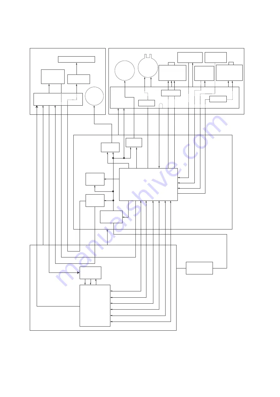
2-3-3 Scanner PWB
Figure 2-3-5Scanner PWB block diagram
Image scanner
unit (ISU)
Scanner PWB
Regulator
LAMP
CPU
Control PWB
ASIC
AFE
Power save
circuit
Power source
PWB
Optional document
processor (DP)
Exposure lamp
ISU
motor
CCD PWB
Home
position
sensor
Inverter
PWB
Driver
Driver
Driver
Motor
driver
Motor
driver
FEEDCLN
DPDETN
PRESOLN
RELSOLN
P
AGESET
OPSWN
ORGSWN
REVSOLN
+3.3V1
+24V4
LAMP
HPSWN
+12V
CSI
+5V1
+3.3V1
+24V1
DP driver PWB
DP timing
sensor
DP original
sensor
DP
open/close
sensor
DP
paper
feed
motor
DP
paper
feed
clutch
DP switchback
feedshift
solenoid
DP switchback
pressure
solenoid
Содержание KM-2810
Страница 1: ...SERVICE MANUAL Published in May 2009 2H9SM060 First Edition KM 2810 ...
Страница 3: ...Revision history Revision Date Replaced pages Remarks ...
Страница 4: ...This page is intentionally left blank ...
Страница 10: ...This page is intentionally left blank ...
Страница 18: ...2H9 1 1 6 This page is intentionally left blank ...
Страница 22: ...2H9 1 2 4 5 Remove nine tapes Figure 1 2 5 Tape Tapes Tapes Tapes Tapes ...
Страница 24: ...2H9 1 2 6 This page is intentionally left blank ...
Страница 105: ...2H9 1 5 15 7 Unhook four hooks and then remove the scanner unit Figure 1 5 19 Scanner unit Hooks Hooks ...
Страница 138: ...2H9 1 5 48 This page is intentionally left blank ...
Страница 157: ...2H9 2 1 17 Figure 2 1 24 Paper exit section block diagram EXITN YC19 3 Fuser unit Exit sensor Control PWB ...
Страница 162: ...2H9 2 2 4 This page is intentionally left blank ...
Страница 174: ...2H9 2 3 12 This page is intentionally left blank ...
Страница 178: ...2H9 2 4 4 This page is intentionally left blank ...
Страница 179: ......
Страница 180: ......


