background image

2PG/2PH

1-5-23

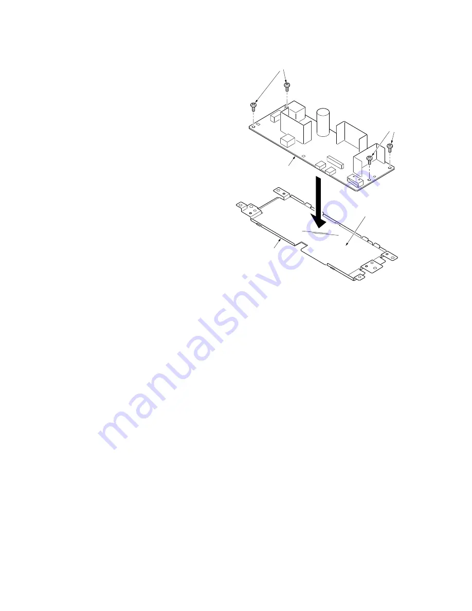
6. Remove four screws and then remove the 

power source plate from the power source 
PWB.

7. Check or replace the power source PWB 

and refit all the removed parts.
Caution: The power source film must be 
installed in the specified position.

Figure 1-5-32

Power source PWB

Screws

Screws

Power source plate

Power source film

Содержание ECOSYS P2035d

Страница 1: ...SERVICE MANUAL Published in Nobember 2013 842PH111 2PHSM061 Rev 1 ECOSYS P2035d ECOSYS P2135d...

Страница 2: ...BATTERIE EST REMPLACEE PAR UN MODELE DE TYPE INCORRECT METTRE AU REBUT LES BATTERIES UTILISEES SELON LES INSTRUC TIONS DONNEES Il peut tre ill gal de jeter les batteries dans des eaux d gout municipal...

Страница 3: ...Revision history Revision Date Pages Revised contents 1 5 Nobember 2013 1 1 1 Change First print time for high model Change Warm up time...

Страница 4: ...This page is intentionally left blank...

Страница 5: ...sonnel to ensure the safety of their customers their machines as well as themselves during maintenance activities Service personnel are advised to read this booklet carefully to familiarize themselves...

Страница 6: ...this symbol CAUTION Bodily injury or damage to property may result from insufficient attention to or incorrect com pliance with warning messages using this symbol Symbols The triangle symbol indicates...

Страница 7: ...or dusty place This may cause fire or electric shock Do not install the copier near a radiator heater other heat source or near flammable material This may cause fire Allow sufficient space around th...

Страница 8: ...carefully Always check that the copier is correctly connected to an outlet with a ground connection Check that the power cable covering is free of damage Check that the power plug is dust free If it i...

Страница 9: ...caution labels that should be present on the machine according to the instruction handbook are clean and not peeling Replace with new ones if necessary Handle greases and solvents with care by followi...

Страница 10: ...This page is intentionally left blank...

Страница 11: ...Black dots 1 4 11 5 Black horizontal streaks 1 4 11 6 Black vertical streaks 1 4 12 7 Unsharpness 1 4 12 8 Gray background 1 4 12 9 Dirt on the top edge or back of the paper 1 4 13 10 Undulated print...

Страница 12: ...nloading the firmware from the memory card 1 6 2 2 1 Mechanical Construction 2 1 1 Paper feed conveying section 2 1 1 1 Cassette paper feed section 2 1 1 2 MP tray paper feed section 2 1 2 3 Paper con...

Страница 13: ...4 JIS B5 A5 Follio Legal Letter Oficio II Statement Executive A6 B6 ISO B5 Envelope C5 Envelope 10 Envelope 9 Envelope 6 3 4 Envelope Monarch Envelope DL Hagaki Ofuku Hagaki 16K Yokei 2 Yokei 4 Custom...

Страница 14: ...C 405F5 360 MHz Supported OS Windows XP Windows XP Professional Windows Server 2003 Windows Server 2003 x64 Edition Windows Vista x86 Edition Windows Vista x64 Edition Windows 7 x86 Edition Windows 7...

Страница 15: ...7 9 6 10 11 12 13 14 8 5 1 Top cover 2 Paper stopper 3 Top tray 4 Operation panel 5 Right side cover 6 Cassette 7 Front cover 8 MP tray 9 Sub tray 10 Optional interface slot cover 11 USB interface co...

Страница 16: ...2PG 2PH 1 1 4 2 Operation panel Figure 1 1 2 1 2 3 4 5 6 7 8 1 Ready indicator 2 Attention indicator 3 Toner indicator 4 Data indicator 5 Paper indicator 6 Jam indicator 7 Cancel key 8 GO key...

Страница 17: ...7 Paper path Light path Paper path option 1 Cassette 2 MP tray 3 Paper feed conveying section 4 Toner container 5 Developing unit 6 Main charger unit 7 Drum unit 8 Laser scanner unit 9 Transfer separa...

Страница 18: ...2PG 2PH 1 1 6 This page is intentionally left blank...

Страница 19: ...nd cool or hot direct air Avoid places subject to dust and vibrations Choose a surface capable of supporting the weight of the machine Place the machine on a level surface maximum allowance inclinatio...

Страница 20: ...3 16 18 19 17 15 15 1 Printer 2 Outer case 3 Bottom pad L 4 Bottom pad R 5 Machine cover 6 Top pad L 7 Top pad R 8 Spacer 9 Toner container 10 Plastic bag 11 Power cord 12 Pad 13 Plastic bag 14 Instal...

Страница 21: ...2PG 2PH 1 2 3 1 Removing the tapes Procedure 1 Remove three tapes Figure 1 2 3 Tape Tape Tape...

Страница 22: ...rt the expanded memory into the mem ory socket so that the notches on the mem ory align with the corresponding protrusions in the slot The memory module is secured to the mem ory socket with the clamp...

Страница 23: ...he memory card into the memory card slot Push it in all the way 5 Secure the optional interface slot cover by using two screws 6 Format the memory card before use To format the memory card Send the fo...

Страница 24: ...e to the printer and the network interface card 2 Open the rear cover Figure 1 2 8 3 Remove two screws and then remove the optional interface slot cover 4 Insert the network interface card into the ne...

Страница 25: ...ich are activated by using the keys on the operation panel or by com manding from a PC 1 Executing a service mode Printing a status page for service purpose See page 1 3 2 Printing an event log EVENT...

Страница 26: ...30286 86000086 02000000 02020202 02020202 03030303 03030303 03030303 03030303 03000000 03030303 03030303 SPD1 0203040508090A0B0C0D0F101112131415161718191A1B1C1D1E1F202122235E 00000000 00000000 0000000...

Страница 27: ...000000 00000000 00000000 00000000 00000000 00000000 00000000 00000000 00000000 00000000 00000000 00000000 00000000 00000000 00000000 00000000 00000000 00000000 00000000 00000000 00000000 00000000 0000...

Страница 28: ...ror displayed only when any error has occurred 01 ID error 02 Version error 03 Checksum error 04 NVRAM crush error 9 Printable area setting Top offset Left offset Page length Page width 10 Left offset...

Страница 29: ...r type attributes Paper type setting value from 1 to 28 density unused paper type are always 0x00 23 Memory SPD information slot 1 2 to 6 bytes 8 to 36 bytes 94 to 95 bytes total 32 bytes 24 DRT corre...

Страница 30: ...on the frequency of paper misfeeds self diag nostic errors and replacements Procedure 1 Connect the USB cable between printer and PC Figure 1 3 3 2 Connect the power cord 3 Turn printer power on Make...

Страница 31: ...J32 0 J40 0 J41 0 J42 0 Released 20 January 2010 Count Event Count Service Code 8 11234 01 6000 7 10000 01 6000 6 9999 01 6000 5 9998 01 6000 4 9997 01 6000 3 9996 01 6000 2 9995 01 6000 1 9994 01 600...

Страница 32: ...ICR mode bit 7 Not used Second byte Displayed in OEM mode only 4 Control PWB firmware version 5 Control PWB firmware release date 6 Total page counter 7 Printer serial number 8 Paper Jam Log Count Eve...

Страница 33: ...oes not pass the paper feeder 1 s PF paper feed sensor Cassette 2 32 32 Paper remains at the paper feeder 1 s PF paper feed sensor when power is turned on Cassette 2 32 40 Paper does not arrive at the...

Страница 34: ...l of paper type Hexadecimal 01 Plain 02 Transparency 03 Preprint 04 Labels 05 Bond 06 Recycle 07 Vellum 08 Rough 09 Letterhead 0A Color 0B Prepunched 0C Envelope 0D Cardstock 10 Thick 11 High quality...

Страница 35: ...tectable The toner replacement log is triggered by toner empty This record may contain such a reference as the toner container is inserted twice or a used toner con tainer is inserted Code of maintena...

Страница 36: ...er con tainer NOTE It is not logged if 100 or more counts are not added to the count at the last error g Paper jam h Self diagnostic error i Maintenance item replacing Indicates the log counter of pap...

Страница 37: ...MK 182 for 120 V specifications Maintenance kit MK 180 for 230 V specifications Maintenance kit MK 184 for 240 V specifications High model Maintenance kit MK 172 for 120 V specifications Maintenance...

Страница 38: ...2PG 2PH 1 3 14 This page is intentionally left blank...

Страница 39: ...no paper sheets are fed at all the printer automatically goes offline and the jam indicator will flash rapidly Status Monitor or COMMAND CENTER can indicate the location of the paper jam the componen...

Страница 40: ...isfeed detection condition Figure 1 4 2 Peper feeder 1 Option Peper feeder 2 Option Printer 1 Registration sensor 2 Paper sensor 3 MP paper sensor 4 Paper exit sensor 5 PF paper sensor 6 PF paper feed...

Страница 41: ...which automatically halts the printer when an error is detected The four indicators Jam Paper Attention Toner are simultaneously lit then indicate a specific error by the combination of the four indi...

Страница 42: ...ndicator 2 3 4 5 6 7 8 9 0 F 2 6 1 1 6 s 1 6 s 0 8 s 0 8 s 0 8 s 0 8 s 0 8 s 0 8 s Repeat Example of self diagnostic code 2610 Refer to the following code conversion table Code conversion table Indica...

Страница 43: ...ace the control PWB See page 1 5 19 Defective harness between PF main PWB YC5 and paper feeder interface con nector or improper connector insertion Reinsert the connector Also check for conti nuity wi...

Страница 44: ...ive harness between PF paper feed motor and PF main PWB YC4 or improper connector insertion Reinsert the connector Also check for conti nuity within the connector harness If none remedy or replace the...

Страница 45: ...r contact in the fuser thermistor con nector terminals Reinsert the connector See page 1 5 16 Broken fuser thermis tor wire Replace the fuser unit See page 1 5 16 Fuser thermistor installed incorrectl...

Страница 46: ...See page 1 5 19 Defective expanded memory DIMM Replace the expanded memory DIMM See page 1 2 4 F030 Control PWB general failure Defective control PWB Turn the power switch off on to restart the printe...

Страница 47: ...e page 1 4 11 See page 1 4 11 See page 1 4 11 6 Black vertical streaks 7 Unsharpness 8 Gray background 9 Dirt on the top edge or back of the paper 10 Undulated print ing at the right edge scanning sta...

Страница 48: ...heck the high voltage PWB visually and correct or replace if necessary See page 1 5 25 Defective laser scanner unit Replace the laser scanner unit See page 1 5 30 Defective control PWB Replace the con...

Страница 49: ...he one that satisfies the paper specifica tions Defective transfer roller installation The transfer roller must be supported by the bushes at the both ends Clean the bush to remove oil and debris Repl...

Страница 50: ...es at the both ends Clean the bush to remove oil and debris Replace the transfer roller if necessary See page 1 5 14 Defective transfer bias output Replace the high voltage PWB or control PWB See page...

Страница 51: ...the drum and developing unit and the fuser unit inlet Clean these areas and parts to remove toner Defective transfer roller If the transfer roller is contaminated with toner clean the trans fer rolle...

Страница 52: ...nector Also check for continuity within the con nector harness If none remedy or replace the harness Defective control PWB Replace the control PWB See page 1 5 19 3 Left cooling fan motor does not ope...

Страница 53: ...ol PWB Replace the control PWB See page 1 5 19 9 Eraser lamp does not turn on Defective harness between eraser lamp YC701 and control PWB YC316 or improper connector inser tion Reinsert the connector...

Страница 54: ...d at one time Check if the separator pad or MPF separation pad is worn Replace the separator pad if it is worn Check if the paper is curled Replace the paper 5 Paper jams Check if the paper is excessi...

Страница 55: ...e original screws If the types and the sizes of screws are not known refer to the PARTS LIST 2 Drum Note the following when handling or storing the drum When removing the drum unit never expose the dr...

Страница 56: ...A black colored band when seen through the left side window A shiny or gold colored band when seen through the right side window The above will reveal that the toner container is a genuine Kyocera bra...

Страница 57: ...cedure 1 Open the top cover 2 Remove two screws Figure 1 5 3 3 Extract the boss from the hole 4 Unhook the A hook 5 Unhook two B hooks 6 Remove the connector 7 Remove the top cover Figure 1 5 4 Top co...

Страница 58: ...refitting the right and left covers Procedure 1 Remove the top cover See page 1 5 3 2 Remove the cassette See page 1 5 6 3 Open the front cover 4 Unhook seven hooks and then remove the right cover Fi...

Страница 59: ...2PG 2PH 1 5 5 5 Unhook seven hooks and then remove the left cover Figure 1 5 6 Left cover Hooks...

Страница 60: ...he paper feed assembly paper feed roller and pickup roller Procedure 1 Remove the cassette Figure 1 5 7 2 Slide the feed shaft 3 While pressing the lever and then remove the paper feed roller assembly...

Страница 61: ...it all the removed parts When refitting the paper feed roller assem bly be sure to align the paper feed roller pivot with the slotted hole on the feed shaft Figure 1 5 9 Paper feed roller assembly Pap...

Страница 62: ...move the cassette See page 1 5 6 2 Push the bottom plate down until it locks 3 Unhook two hooks and then remove the retard guide Figure 1 5 10 4 Remove the retard roller assembly Figure 1 5 11 Retard...

Страница 63: ...retard roller assembly and refit all the removed parts Caution Before refitting the retard roller assembly firmly install the spring onto the projection of the retard roller assembly Figure 1 5 12 Spr...

Страница 64: ...aper feed roller 3 Figure 1 5 13 5 Check or replace the MP paper feed roller and refit all the removed parts When refitting the MP paper feed roller be sure to align the MPF feed shaft pivot with the...

Страница 65: ...cover 3 Remove the developing unit with toner con tainer 4 Check or replace the developing unit and refit all the removed parts 5 When the developing unit is replaced with a new one carry out the fol...

Страница 66: ...Drum section 1 Detaching and refitting the drum unit Procedure 1 Remove the developing unit See page 1 5 11 2 Remove the drum unit 3 Check or replace the drum unit and refit all the removed parts Fig...

Страница 67: ...2 Remove the tape 3 While pushing on the main plate 1 slide the main charger unit 2 Figure 1 5 17 4 Remove the main charger unit by lifting it 5 Check or replace the main charger unit and refit all t...

Страница 68: ...ting the transfer roller Procedure 1 Remove the developing unit See page 1 5 11 2 Remove the drum unit See page 1 5 12 3 Slide the paper chute guide and unhook the hooks 4 Remove the paper chute guide...

Страница 69: ...and refit all the removed parts Caution When refitting the transfer roller be careful about following point Push the release lever to raise the lever end then insert the front of gear Z16 under the re...

Страница 70: ...the fuser unit Procedure 1 Remove the outer covers See page 1 5 3 2 Remove two connectors 3 Release the wires form wire clamps Figure 1 5 22 4 Remove the connector Figure 1 5 23 Connector Fuser heater...

Страница 71: ...5 17 5 Remove the rear cover Figure 1 5 24 6 Remove two screws and then remove the fuser unit 7 Check or replace the fuser unit and refit all the removed parts Figure 1 5 25 Rear cover Screw Screw Fu...

Страница 72: ...reasing the fuser pressure could cause loose toner fusing Procedure 1 Remove the cassette See page 1 5 6 2 Open the duplex cover 3 Slide the fuser lever R and L Normal Flush with the front of the mach...

Страница 73: ...itting the control PWB Procedure 1 Remove the right cover See page 1 5 4 2 Remove fourteen connectors form the con trol PWB 3 Release the wires from the wire clamps Figure 1 5 27 Connectors Thirteen C...

Страница 74: ...Remove five screws 5 Remove three connectors form the control PWB 6 Unhook the hook and then remove the con trol PWB assembly Figure 1 5 28 Hook Screws Control PWB assembly Control PWB Screw Screws C...

Страница 75: ...PWB 8 Check or replace the control PWB and refit all the removed parts To replace the control PWB remove the EEPROM U300 from the old control PWB and mount it to the new control PWB Figure 1 5 29 Scr...

Страница 76: ...e four connectors Figure 1 5 30 4 Remove four P tight screws two screws and ground terminal 5 Remove the power source PWB assembly from the high voltage PWB s connector Figure 1 5 31 Connector Connect...

Страница 77: ...urce plate from the power source PWB 7 Check or replace the power source PWB and refit all the removed parts Caution The power source film must be installed in the specified position Figure 1 5 32 Pow...

Страница 78: ...he panel cover 3 Remove the operation panel PWB 4 Remove the connector 5 Check or replace the operation panel PWB and refit all the removed parts Be sure to fit the GO and Cancel keys in the appropria...

Страница 79: ...1 5 12 3 Remove the cassette See page 1 5 6 4 Remove the outer covers See page 1 5 3 5 Remove the power source PWB See page 1 5 22 6 Turn the printer with the bottom side up 7 Remove the stop ring 8 R...

Страница 80: ...2PG 2PH 1 5 26 11 Remove four screws 12 Unhook three hooks and then remove the lower base cover Figure 1 5 36 Screws Screws Hook Hook Hook Lower base cover Lower base cover...

Страница 81: ...pin Figure 1 5 37 15 Remove two connectors and then remove the high voltage PWB 16 Remove the cassette pin holder from the high voltage PWB Figure 1 5 38 Spring Cassette pin Cassette pin holder High v...

Страница 82: ...he high voltage PWB Each interface is firmly in contact with each spring The bias contact pin must be installed in the specified position The cassette pin must be inserted in the cassette pin holder F...

Страница 83: ...rocedure 1 Remove the right cover See page 1 5 4 2 Remove the connector Figure 1 5 40 3 Remove the M3 screw and two M4 screws 4 Remove the main motor 5 Check or replace the main motor and refit all th...

Страница 84: ...fitting the laser scanner unit Procedure 1 Remove the right cover See page 1 5 4 2 Remove the connector from the control PWB 3 Release the wire clamp 4 Draw in the connector inside Figure 1 5 42 Clamp...

Страница 85: ...2PG 2PH 1 5 31 5 Remove four screws and then remove the laser scanner unit 6 Check or replace the laser scanner unit and refit all the removed parts Figure 1 5 43 Screws Screws Laser scanner unit...

Страница 86: ...fitting the eraser lamp Procedure 1 Remove the laser scanner unit See page 1 5 30 2 Remove the connector 3 Remove the eraser lamp 4 Check or replace the eraser lamp and refit all the removed parts Fig...

Страница 87: ...g the left and right cooling fan motors When detaching or refitting the left and or right cooling fan motors be careful of the airflow direction intake or exhaust Figure 1 5 45 Left cooling fan motor...

Страница 88: ...2PG 2PH 1 5 34 This page is intentionally left blank...

Страница 89: ...codes Figure 1 6 1 Software ID Compression S2PH_1000001021 cmp Firmware file name example Product code 2PG Low model 2PH High model Pause underscore Pause period Build number Update history Classific...

Страница 90: ...an accidental power failure etc the control PWB may have to be replaced Do not download the system firmware and engine firmware at one time Store the either firmware in a memory card and download one...

Страница 91: ...8 s 0 8 s Repeat Repeat Supervisor mode Deleting and writing data Downloading complete Receiving data Downloading start Repeat Repeat End End 4 8 s 4 8 s Repeat Repeat Pattern 1 Pattern 2 Pattern 3 D...

Страница 92: ...optional interface slot cover by using two screws 10 Close the rear cover 11 Turn power on again Check the printer gets ready and Ready indicator is lit 12 Print a status page See page P 1 3 2 13 Con...

Страница 93: ...to the transfer separation section 1 Cassette paper feed section Figure 2 1 1 Cassette paper feed section Figure 2 1 2Cassette paper feed section block diagram 1 9 7 3 4 5 2 6 8 10 11 1 Pickup roller...

Страница 94: ...paper feed roller 2 MPF separation pad 3 MPF separator 4 MPF bottom plate 5 MPF friction pad 6 MP paper sensor 7 Actuator MP paper sensor 8 MPF frame 9 MPF guide R L 10 MPF base 11 MPF middle tray 12...

Страница 95: ...tion block diagram 1 4 3 5 2 1 Lower registration roller 2 Upper registration roller 3 Registration sensor 4 Actuator registration sensor 5 Feed pulley MMOTRDYN REGDRN Registration clutch Main motor C...

Страница 96: ...h as a screwdriver etc resulting in a print quality problem Also finger prints can cause deterioration of the OPC layer therefore the drum in the drum unit must be handled with care Substances like wa...

Страница 97: ...ization after a long run Therefore the charger wire must be cleaned at a specific interval Cleaning the charging wire prevents print quality problems such as black streaks Figure 2 1 8 Main charger un...

Страница 98: ...avelength beam is dispersed as the polygon motor revolves to reflect the laser beam over the drum Various lenses and mirror are housed in the laser scanner unit adjust the diameter of the laser beam a...

Страница 99: ...re 2 1 11 Laser scanner unit 1 2 3 8 9 10 4 5 6 7 1 Polygon motor mirror 2 Laser diode APC PWB 3 Collimator lens 4 Cylindrical lens 5 F lens 6 F lens 7 PD mirror 8 SOS lens 9 Pin photo diode sensor PD...

Страница 100: ...en a positive charge The positively charged toner is then attracted to the areas of the drum which was exposed to the laser light The gap between the drum and the magnet sleeve is approximately 0 32 m...

Страница 101: ...voltage PWB is applied to the transfer roller for transfer charging Paper after transfer is separated from the drum Figure 2 1 14 Transfer separation section Figure 2 1 15 Transfer separation section...

Страница 102: ...lly cleaned it then must be cleaned to the electrically neutral state This is necessary to erase any residual positive charge ready to accept the uniform charge for the next print process The residual...

Страница 103: ...t with its surface These separators claws prevent the paper on which toner has been fused from being wound around the heat roller causing paper jam The press roller is made of the heat resistant silic...

Страница 104: ...ection block diagram N L THERM HEATN SLEEP ZCROSS YC102 1 YC102 3 YC103 6 YC103 7 YC103 8 YC311 5 YC311 6 YC311 3 YC311 16 Fuser unit Fuser thermistor Fuser heater lamp Fuser thermal cutout Power sour...

Страница 105: ...e fuser unit and is led by the guide comprised of the rear cover frame and the FD cover guide finally reaching the upper FD roller The paper is delivered to the top tray by the rota tion of the upper...

Страница 106: ...2PG 2PH 2 1 14 Figure 2 1 21 Paper exit section block diagram EXITN YC307 4 Fuser unit Exit sensor Control PWB...

Страница 107: ...when duplex printing Figure 2 1 22 Duplex conveying section Figure 2 1 23 Duplex paper conveying section block diagram 1 9 10 2 3 5 6 7 4 8 1 DU cover B 2 DU holder 3 Middle pulley B 4 DU roller 5 DU...

Страница 108: ...2PG 2PH 2 1 16 This page is intentionally left blank...

Страница 109: ...n charging developing bias and transfer bias 4 Operation panel PWB Consists the LED indicators and key switches 5 APC PWB Generates and controls the laser beam 6 PD PWB Controls horizontal synchronizi...

Страница 110: ...in the cassette 6 MP paper sensor Detects the presence of paper on the MP tray 7 Exit sensor Detects paper jam in the fuser or duplex conveying section 8 Toner sensor Detects the quantity of toner in...

Страница 111: ...oling fan motor Cools the interior of machine 5 Registration clutch Controls the secondary paper feed 6 Paper feed clutch Controls the paper cassette paper feed 7 Developing clutch Controls the toner...

Страница 112: ...2PG 2PH 2 2 4 This page is intentionally left blank...

Страница 113: ...ock diagram 5V1 SLEEP 24V1 24V2 FAN 3 3V1 ZCROSS HEATN THERM Power source PWB Left cooling fan motor Fuser thermistor Fuser thermal cutout Fuser unit Switching regulator circuit Zero cross signal circ...

Страница 114: ...I 0 24 V DC Left cooling fan motor On Off 4 THERM O Analog Fuser thermistor detection voltage 5 3 3V I 3 3 V DC 3 3 V DC power source 6 HEATN I 0 3 3 V DC Fuser heater lamp On Off 7 SLEEP I 0 3 3 V D...

Страница 115: ...ROM 3 3 V Laser scanner unit I F KUIO I F Optional expanded memory DIMM Engine I F Duplex solenoid Developing clutch MP paper feed solenoid Registration clutch Paper feed clutch Paper feed sensor MP p...

Страница 116: ...1 1 1 1 1 1 19 5 5 6 6 1 2 2 1 3 1 3 1 4 3 A1 A2 B1 B2 2 13 A29 A30 B29 B30 5 1 1 4 2 3 1 4 51 52 1 2 99 100 49 50 1 26 25 8 1 1 1 2 3 50 YC319 YC306 YC309 YC308 YC305 YC313 YC318 YC311 YC301 YC304 YC...

Страница 117: ...3 MMOTRDYN I 0 3 3 V DC Main motor ready signal 4 MMOTCLK O 0 3 3 V DC pulse Main motor clock signal 5 REMOTEN O 0 3 3 V DC Main motor On Off YC306 1 3 3V2 O 3 3 V DC 3 3 V DC power source Connected t...

Страница 118: ...alog Fuser thermistor detection voltage 17 24V3 O 24 V DC 24 V DC power source 18 SGND Ground YC312 1 3 3V1 O 3 3 V DC 3 3 V DC power source Connected to the waste toner sensor 2 TNFULL I 0 3 3 V DC W...

Страница 119: ...ower source Connected to the laser scanner unit 2 PGND Ground 3 PLGDRN O 0 3 3 V DC Polygon motor On Off 4 PLGRDY I 0 3 3 V DC Polygon motor ready signal 5 PLGCLK O 0 3 3 V DC pulse Polygon motor cloc...

Страница 120: ...2PG 2PH 2 3 8 This page is intentionally left blank...

Страница 121: ...5 6 7 8 1 2 3 4 5 6 7 8 Control PWB Registration sensor Paper sensor MP paper sensor Registration clutch Paper feed clutch Developing clutch Duplex solenoid High voltage PWB Power source PWB Main moto...

Страница 122: ...t 24 99 mm 1 Upper registration roller 37 68 mm 1 1 2 Lower registration roller 62 8 mm 2 1 2 Developing roller developing unit 45 216 mm 1 3 4 Transfer roller 73 162 mm 2 7 8 Heat roller fuser unit 7...

Страница 123: ...more to your PC If the animation is not displayed you should get the latest version from Adobe site http www adobe com downloads Indication Contents Control PWB EEPROM error Paper feeder communication...

Страница 124: ...fuser thermistor wire Zero cross signal error Control PWB checksum error Control PWB RAM checksum error Control PWB general failure Control PWB engine communication error Control PWB engine checksum e...

Страница 125: ...2PG8NL0 072PG8NL DK 150 DV 160 E Maintenance kit 240 V specifications MK 184 MAINTENANCE KIT 1702PG8AS0 072PG8AS DK 150 DV 164 AO Maintenance part name Part No Alternative part No Name used in service...

Страница 126: ...2PG 2PH 2 4 6 This page is intentionally left blank...

Страница 127: ...517 Fax 64 9 415 4597 KYOCERA Document Solutions Asia Limited 16 F Mita Centre 552 566 Castle Peak Road Tsuenwan NT Hong Kong Phone 852 2610 2181 Fax 852 2610 2063 KYOCERA Document Solutions China Cor...

Страница 128: ...9084950 is a trademark of KYOCERA Corporation KYOCERA Document Solutions Deutschland GmbH Otto Hahn Strasse 12 40670 Meerbusch Germany Phone 49 2159 9180 Fax 49 2159 918100 KYOCERA Document Solutions...

Отзывы: