3-30
MD1034
MD1036
5
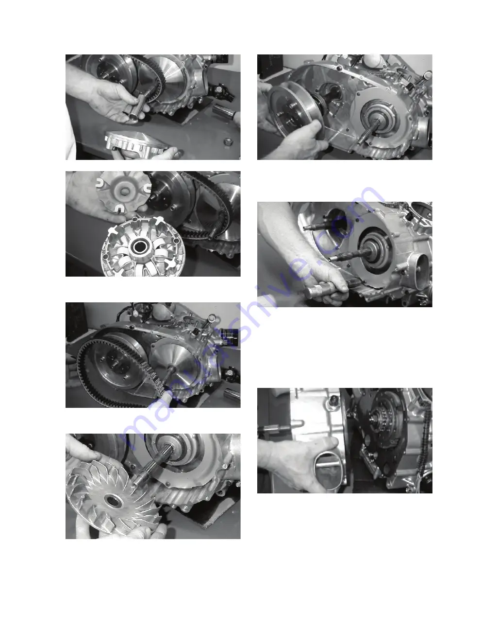
. Remove the V-belt.
MD1118
6. Remove the fixed drive face.
MD1094
7.
Remove the nut holding the driven pulley assem-
bly; then remove the driven pulley assembly.
MD1068
8. Using an impact screwdriver, remove the three
Phillips-head cap screws holding the air intake
plate. Remove the air intake plate.
MD1092
9. Remove the cap screws holding the clutch cover
onto the right-side crankcase half. Note the posi-
tions of the different-lengthed cap screws for
installing purposes
.
10. Using a rubber mallet, loosen
the clutch cover;
then pull it away from the right-side crankcase
half. Account for two alignment pins and gasket.
MD1115
D. Gear Shift Position Switch
E. Centrifugal Clutch Assembly
F. Oil Pump Drive Gear
G. Oil Pump Driven Gear
NOTE: Steps 1-10 in the preceding sub-section
must precede this procedure.
Содержание MXU 450i
Страница 17: ...Oil level stick...
Страница 23: ...Low range High range Neutral Reverse...
Страница 25: ...1 mm 0 039 in...
Страница 126: ...A B...
Страница 127: ...LCD Gauge Connector LCD Gauge Connector...
Страница 134: ...9 4 NOTES...
Страница 135: ......
Страница 161: ...11 EFI SYSTEM 11 20 MXU 450i ATV FI DIAGNOSTIC TOOL OPERATION INSTRUCTIONS 3620A LEB2 E00 ENGLISH VERSION Version V1 0 7...
Страница 167: ...11 EFI SYSTEM 11 26 MXU 450i J Press the Enter button and then turn to the first page LKK7 LKK7...


