background image

18    |    kvm-tec

kvm-tec    |    19

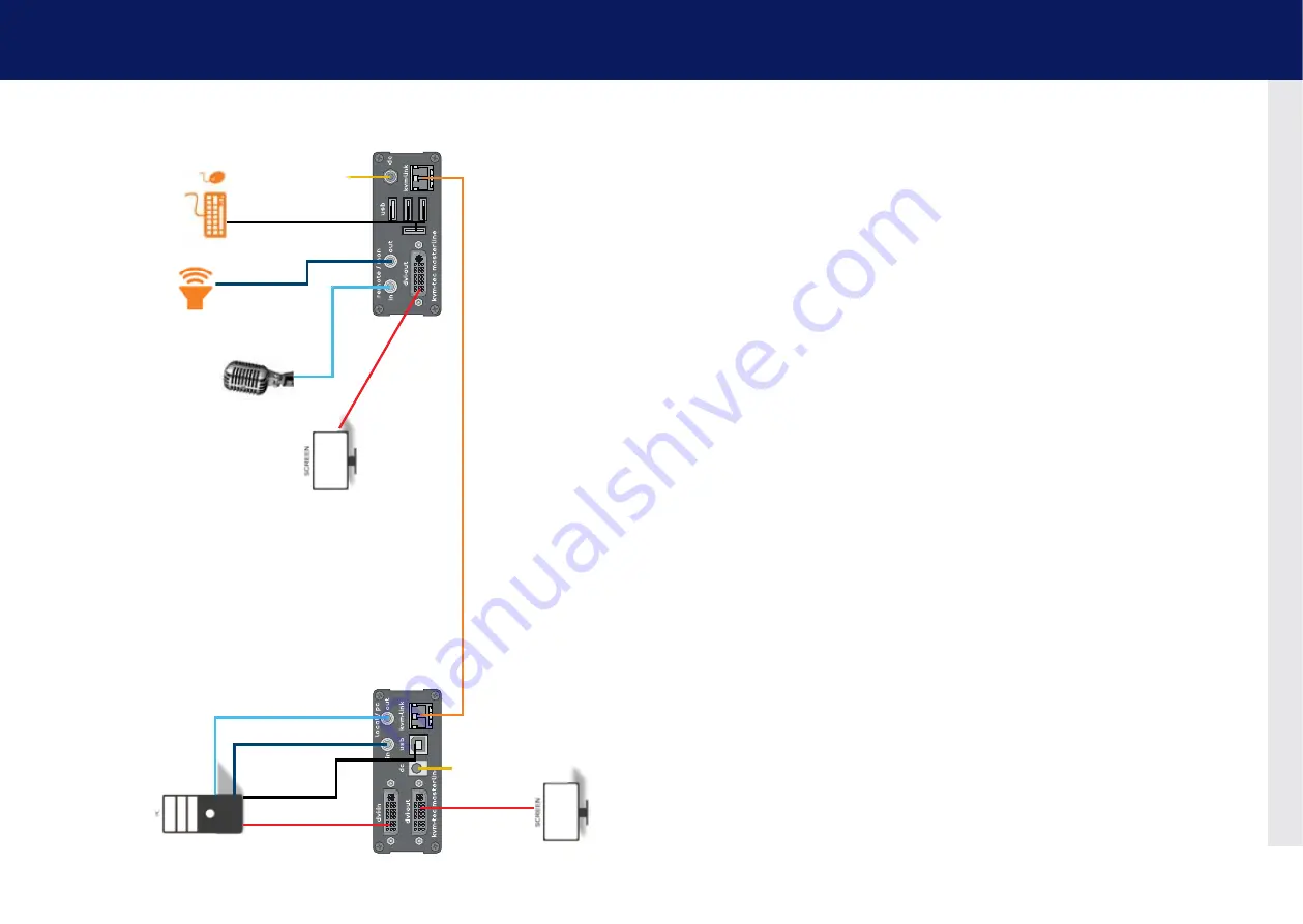
2. installation of the extender

2. installation of the extender

1. 

Po

wer 

plug

12V 1A

fibre

4. DVI in
 from PC

2. USB to PC

4. DVI out
 to Monitor

5. Audio
from PC

6. Audio to PC

fibre

2. USB from
Keyboard and mouse

3. Duple

x Multimode Fiber cable up to 500m/1640 ft

4. D

VI to Monitor

5. Audio
to Speaker

6. Audio fr

om 

Micr

ophone

Quick Installation MVX1-F  FIbER MASTERlINE 


local / CPU – remote/ COn

1. 

 Connect the CON / Remote and the CPU / Local Unit to the included 12V 1A power supply.

2. 

 Now connect the USB cable to a USB port on your PC and connect the other end of the USB cable 
to the CPU / Local Unit. Connect keyboard and mouse to the CON / Remote Unit.

3. 

 Connect the CPU / Local and the CON / Remote Unit with a fiber cable.

4. 

Now connect the DVI cable to the DVI socket of the PC and the other end to the DVI socket of the 
CPU / Local Unit (DVI-in). Then connect the monitor to the CON / Remote Unit with a DVI cable.

5. 

Then connect PC audio out with the audio cable to Local Audio in. Then connect audio / out via the 
audio cable

6. 

Almost done! Now connect the audio cable Local Audio / out to the PC Audio in and Remote Audio 
/ out with the audio cable to the microphone

HAVE FUN - your kvm-tec Extender is now in use for many years ( MTBF approx 10 years) 

1. 

Po

wer 

plug

12V 1A

Содержание Master Line MVX Series

Страница 1: ...Channel www kvm tec com line master kvm tec User Manual Masterline MVX 6701 SET 6701L CPU LOCAL 6701R CON REMOTE Masterline fiber MVX F 6801 SET 6801L CPU LOCAL 6801R CON REMOTE connect collaborate communicate control kvm tec C 4 ...

Страница 2: ...settings 23 3 1 Using the On Screen menu 22 3 2 Status menu 23 3 3 Determine the current firmware version 24 3 4 Performing a firmware update 25 3 4 1 Update via a bitmap image 26 3 4 2 Update with USB stick 27 3 4 3 Performing autoupdate 30 3 4 4 Performing network update 31 3 5 Unlock an upgrade 32 3 6 Enable or disable the USB Memory upgrade 33 3 7 Defining what DDC information is used by the P...

Страница 3: ...54 4 4 Viewing the status of all remote units 57 4 5 Viewing the status of all local units 59 4 6 set up dual head or multi head systems 61 4 7 Enable user groups and rights and login access 63 4 8 Auto connect to a free computer after an interruption 64 4 9 Set up a private connection 65 4 10 Enable the User PC Binding mode 66 4 11 Enable the disconnect on PC power down option 67 4 12 Hide info d...

Страница 4: ... Keep all safety information and instructions for future reference and pass them on to subsequent users of the product The manufacturer is not liable for cases of material damage or personal injury caused by incorrect handling or non compliance with the safety instructions In such cases the warranty will be voided This product is not intended for use by persons including children with restricted p...

Страница 5: ... Do not drop or hit the product Unplug all connections before cleaning the product Do not use wipes or chemicals as these could damage the surface Wipe the housing with a damp cloth Electrical electronic parts must not be cleaned Alterations to the product and technical modifications are not permitted 1 3 Technical Specifications Type KVM Extender local unit and remote unit Model Masterline MVX1 M...

Страница 6: ...or 12 V power supply 7 dvi out DVI connection to monitor 8 Power Status LED Displays the status of the extender Remote Extender CON Nr Name Function 9 in Audio In from microphone etc 10 out Audio Out to speakers etc 11 usb USB connections e g for keyboard and mouse 12 dc Connection for 12 V power supply 13 kvm link RJ45 socket Connection for CAT5 6 7 cable or fibre cable 14 dvi out DVI D connectio...

Страница 7: ...een V fast Yes Yellow No Yellow Slow Yes Green Yes Green V fast Yes Main LED RJ45 Socket LEDs 2 1 Unpacking and checking the contents Before using the product for the first time it should be checked for damage In case of damage due to transport inform the carrier immediately Before delivery the product is checked for its function and its operating safety Make sure that the packaging contains the f...

Страница 8: ...tenders It consists of 19 Rack Shelf an alu faceplate and a power supply Rack Mounting Kit RMK FRN Part No 6132 The rack mounting kit RMK FRN is used to mount kvm tec Smartline SVX and Masterline MVX extenders It is equipped with rack shelf faceplate and 2 power supply units which are summarized in a redundancy module Under Desk Mounting Kit Part No 6135 The Under Desk Mounting kit is for underdes...

Страница 9: ...f the USB cable to the CPU Local Unit Connect keyboard and mouse to the CON Remote Unit 3 Connect the CPU Local and the CON Remote Unit with a network cable 4 Now connect the DVI cable to the DVI socket of the PC and the other end to the DVI socket of the CPU Local Unit DVI in Then connect the monitor to the CON Remote Unit with a DVI cable 5 Then connect PC audio out with the audio cable to Local...

Страница 10: ...port on your PC and connect the other end of the USB cable to the CPU Local Unit Connect keyboard and mouse to the CON Remote Unit 3 Connect the CPU Local and the CON Remote Unit with a fiber cable 4 Now connect the DVI cable to the DVI socket of the PC and the other end to the DVI socket of the CPU Local Unit DVI in Then connect the monitor to the CON Remote Unit with a DVI cable 5 Then connect P...

Страница 11: ...reen The monitor will displays your computer s desktop or any open applications 2 5 Replacing the SFP module The MVX1 F is delivered with a multimode SFP module To replace an SFP module with a different SFP module 1 Remove the black dust protector from the SFP module 2 Pull the metal latch of the SFP module forwards until it is at a right angle 3 Replace the SFP module with the other module Put th...

Страница 12: ... firmware M Option Overview Overview of all upgrades O DDC Option DDC Option Fixed ice position 1020 x 1080 W Network Settings Network Settings G ExtenderSettings Settings Extender L Switching List List of all extenders in the switching system Q Exit Exit kvm tec 23 3 Extender menu settings 3 2 Status menu In the Status Menu the current status of the extender connection is displayed It provides in...

Страница 13: ...http www kvm tec com en support firmware download html Each update file is accompanied by a detailed description of the update process There are four ways to perform an update 1 update via a bitmap image 2 update from the USB stick 3 automatic update 4 network update To perform a firmware update 1 Make sure the main menu is open 2 Press the U key The Update menu appears Press the N key to do a net...

Страница 14: ...ve been completed and make sure that you have Never unplug or plug in the devices during the update 3 4 2 Update with USB stick For the update of the USb Stick the following steps are necessary 1 you receive the message that you can plug in the USB stick 2 copy the update file ending in kvm to the USB stick 3 make sure that the update file is directly on the stick and that it is not in any subdire...

Страница 15: ...28 kvm tec kvm tec 29 3 extender menu settings 3 extender menu settings Plug in the USB stick and wait for a moment Wait until all 4 phases have been completed ...

Страница 16: ...to the other The flashing of the LEDs indicates that the update process has been completed the LEDs are then green 3 4 4 Performing network update In the network update the devices that are updated can be marked The information is then sent to the marked units During this process the devices can still be in operation As soon as all updates have been transmitted the marked devices can be restarted ...

Страница 17: ...ave prevents the intrusion of viruses via the USB interface by deactivating mass storage devices 3 5 Unlock an upgrade 1 Make sure that the main menu is open 2 2 press the M button The Options Overview menu opens The device ID will be order the unlock code from your supplier 3 order the activation code from your supplier by entering the 9 digit device ID and enter the serial number of the KVM Exte...

Страница 18: ...ngs after the extender has been restarted Press 4 through 8 to use a predefined resolution which is saved 3 Press ESC to go back to the main menu 3 8 Changing the network settings See chapter Switching Menu Settings 3 9 Changing the extender settings The Extender Settings menu allows the user to change a range of further preferences Three of the selections VGA Audio and RS232 will take you to sub ...

Страница 19: ... The VGA menu appears Press F1 to move the display area up Press F4 to move the display area down Press F2 to move the display area to the left Press F3 to move the display area to the right Press F5 to zoom out Press F6 to zoom in Press space to change the rate of the above mentioned setting This toggles the rate of change between 1 and 10 Press M to switch the video mode between Auto the mode is...

Страница 20: ...olume 1 From the Extender Settings menu press the R key The Remote Settings menu appears 2 Press the A key The Audio Input Gain menu appears Press arrow left right to change volume Press arrow up down to set directio 3 9 2 Enable or disable the USB Compatibility Mode The USB compatibility mode can be enables or disabled To enable disable the USB compatibility mode 1 From the Extender Settings menu...

Страница 21: ...ocal Unit Pinout DCE Pin Function Direction 2 TxD OUT 3 RxD IN 4 DTR IN 5 GND 8 CTS OUT The pin numbers refer to a 9 pin D sub plug The baud rate can be set in the menu There is a universal setting for baud rates up to 9600 which transmits all different RS232 configurations transparently For higher baud rates the following settings are available via the menu Baudrate Parity Stopbits 4800 No 1 9600...

Страница 22: ...sing multimedia applications Not all monitors support this method so by default this option is disabled To turn on monitor synchronization 1 From the Extender Settings menu press the R key The Remote Settings menu appears 2 Press the I key to enable or disable the function 3 Press ESC to go back to the main menu 3 9 7 Locking the main menu The extender menu can be locked When enabled the extender ...

Страница 23: ...y to enable or disable the power saving mode 3 When in power saving mode press any key to return to the menu 3 9 9 Selecting your type of Keyboard The Keyboard Locale menu lets you switch between keyboard layouts for navigating the on screen display menu OSD You can choose between French Azerty English Qwerty and German Qwertz To select a keyboard layout 1 From the Extender Settings menu press the...

Страница 24: ...te Settings menu appears 2 Press the H key The Keyboard Shortcuts menu opens 3 Use the arrows to select a command 4 Press E to edit the shortcut To edit Press a single key Edit the frequency with left and right arrows OR Press a key combination 3 9 10 Changing the Keyboard fallback mode To change the keyboard fallback mode 1 From the Extender Settings menu press the R key The Remote Settings menu ...

Страница 25: ...ther computers can still be accessed via the switching menu To change the order of the computers in this list select the computer then press a number key 1 through 8 to shift it to that number If the password system is active the user currently logged in is displayed at the bottom You can manually logout by pressing the x key or disconnect from the current PC by pressing the d key 3 11 Sharing vid...

Страница 26: ...cess to the Network Settings this option is protected by a user password combination Access is only allowed for users with administrator rights The factory settings provide an administrator user with User admin and Password admin The Master View option allows the administrator to view add edit or remove user console and computer information Press the V key to access the Master View menu The Networ...

Страница 27: ...or select a workstation from the current connected devices 1 Make sure the Master View menu is open see chapter How to access the Network Settings menu Master View and Network Mode 2 Press the O key The Connection Overview menu opens 3 Press the I key The Connection Details window opens Press the D key to force disconnect the selected device connection Press the E key or Enter key to select a PC o...

Страница 28: ...1 Make sure the Master View menu is open see chapter How to access the Network Settings menu Master View and Network Mode 2 Press O to exit the menu 2 Press the U key The User List menu opens Press the A key to add a new user Press the R key to delete the selected user Press the I key to display details about the selected user which may be edited 4 Network Settings 4 Network Settings ...

Страница 29: ... connection of another Master the interrupted Master may reclaim the original connection Admins and private connections can t be interrupted User In the case that a User interrupts the connection of another User the interrupted User may reclaim the original connection Admins Masters and private connections can t be interrupted Groups Each user can join up to 8 user groups Each computer is defined ...

Страница 30: ...onsole Extender Detail menu opens 4 Press the E key to edit the name of the extender 4 5 Viewing the status of all local units The PC Extender List allows you to view all local units in the switching network and their current status To view the status of all local units 1 Make sure the Master View menu is open see chapter How to access the Network Settings menu Master View and Network Mode 2 Press...

Страница 31: ...eve this we assign each PC a different group Department PC Group 1 Team A PC Group 2 Team B PC Group 3 Alex Blair and Charlie are assigned to be members of Group 1 and Group 2 Danny Em and Frankie are assigned to be members of Group 1 and Group 3 4 6 set up dual head or multi head systems If you use multiple monitors with a PC then you can group individual local and remote units together in the Mu...

Страница 32: ...user groups and rights and login access The Passwords option allows to activate user groups and rights and login access For more information about user groups and rights see How to manage user details rights and groups Access to the network settings is always protected by a login and password even when the password system is disabled To enable the password option 1 Make sure the Network Mode menu ...

Страница 33: ... to disable or enable the option 4 9 Set up a private connection The Auto Connect option allows you to set up a private connection with a computer which can t be interrupted by other users To enable the private connection option 1 Make sure the Network Mode menu is open see chapter How to access the switching menu Master View and Network Mode 2 Press the V key to disable or enable the option 3 To ...

Страница 34: ...he disconnect on PC power down option The Auto Connect option allows you to break the connection of any local unit that is connected to a PC that is powered down allowing the remote unit to find a different local extender to connect to To enable the PC Power Down option 1 Make sure the Network Mode menu is open see chapter How to access the switching menu Master View and Network Mode 2 Press the D...

Страница 35: ...r View and Network Mode 2 Press the H key to disable or enable the option 4 13 Reconnect on startup To reconnect on startup 1 Make sure the Network Mode menu is open see chapter How to access the switching menu Master View and Network Mode 2 Press the T key to disable or enable the option 4 14 Video sharing See chapter How to share videos 4 Network Settings 4 Network Settings ...

Страница 36: ...n appears reconnect power supply again If the menu is visible press the O key and choose the resolution of the monitor Then press the assigned number on your keyboard LED is lighting green Screen occurs but the keyboard is not working Plug out in USB of keyboard and wait until driver is installed after few seconds Check all USB connections on both sides Local and Remote If it is still not working ...

Страница 37: ...nitor on the local out of the local Unit Check if local and remote Unit have the correct firmware Check if the DDC is set correctly in the menu under point o Check if the network switch is setup cor rectly and has enough bandwidth Contact kvm tec support Check if other units have the same behaviour kvm tec Support support kvm tec com Phone 43 2253 81912 30 6 1 Requirements for CAT5e 6 7 Cables A C...

Страница 38: ...xisting company network The network switch must fulfil the following specifications 1 Gigabit Switch with true port to port transfer rates of 1 Gigabit second 7 Requirements network Recommended Switches 7 Requirements Network A list of kvm tec tested and recommended switches can be found on our website at www kvm tec com Products Switching System Datasheet recommended Switche ...

Страница 39: ...f environmentally friendly materials which may be disposed through your local recycling facilities By disposing of the packaging and packaging waste in the proper manner you help to avoid possible hazards for the environment and public health CAUTION Do not use solvent containing cleansers Do not use wipes alcohols e g spiritus or chemicals as these could damage the surface To clean the product Cl...

Страница 40: ...e 0043 0 2253 81 912 Fax 0043 0 2253 81 912 99 Email support kvm tec com Web www kvm tec com Find our newest updates and FAQs on our homepage http www kvm tec com support kvm tec Inc USA Sales p 1 213 631 3663 43 225381912 22 email officeusa kvm tec com kvm tec ASIA PACIFIC Sales p 9173573 20204 email sales apac kvm tec com kvm tec China Sales P 86 1360 122 8145 email chinasales kvm tec com ...

Отзывы: