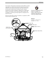
4. Gently press downward on the motor hub until
the drive belt is at proper tension. Adjust the belt
tension for a maximum of
1
⁄
8
" (3 mm) deflection
with moderate finger pressure between the motor
and antenna pulley. Some readjustment may be
necessary if the belt tension results in excessive
antenna reflector vibration.
5. Tighten the holding screws.
4.6.2 Elevation Drive Motor Removal
and Replacement
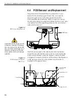
1. Remove the Elevation Motor Molex connector
from the PCB (illustrated in Figure 4-3). Feed the
drive motor cable through the cutout to the front
of the elevation drive assembly support frame.
2. Remove the two machine screws and washers
holding the motor in position. Withdraw the
motor from the elongated slots.
3. Remove (2) screws from the tapped motor
mounting plate and transfer the plate and screws
to the replacement motor. Apply a drop of thread-
locking compound (e.g., Loctite 425 or equivalent)
where each screw protrudes from the plate.
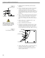
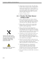
4. Install the new motor with the open holes in the
motor mounting plate behind the slots in the
frame and the motor connector facing down, as
shown in Figure 4-8. Reinstall the machine screws
and washers but do not tighten.
5. Raise the motor and work the toothed drive belt
over the outer lip of the hub. Press down gently on
the motor body while rotating the antenna
reflector up and down to ensure free movement.
6. Adjust the belt tension for a maximum of
1
⁄
8
" (3 mm) deflection with moderate finger
pressure between the hub and gear. Some
readjustment may be necessary if the belt tension
results in excessive antenna reflector vibration.
7. Reconnect the Elevation Motor Molex connector to
the PCB.
4-10
TracVision 4 Installation and Technical Manual
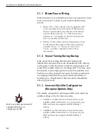
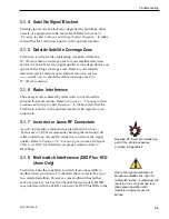
Excessive belt tension may result in
antenna reflector vibration.
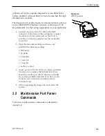
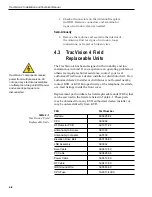
The short screw must go in the
upper left hole on the motor flange
(as viewed from the motor housing
end with the cable extending
down). Refer to Figure 4-8 for
proper screw location.

